Phase synchronization circuit and receiver having the same

a phase synchronization circuit and receiver technology, applied in the direction of digital transmission, pulse automatic control, electrical equipment, etc., can solve the problems of reducing the phase-noise characteristic of the entire pll, and tdc generating quantization nois

Inactive Publication Date: 2009-08-20
KK TOSHIBA
View PDF3 Cites 45 Cited by
  • Summary
  • Abstract
  • Description
  • Claims
  • Application Information

AI Technical Summary

Benefits of technology

[0013]According to an aspect of the invention, there is provided a phase synchronization circuit comprising: a controlled oscillator configured to generate a first oscillation signal and a second oscillation signal that have a common frequency but different phase controlled by a combination of a first control signal and a second control signal; a digital phase frequency detector configured to detect a frequency difference and a first phase difference between a reference signal and the first oscillation signal to generate a first detection signal that accords with the frequency difference and the first phase difference; a digital filter configured to suppress high-frequency components of the first detection signal to obtain th

Problems solved by technology

However, the TDC generates quantization noise, however.
Since its resolution is limited, the TDC generates quantization noise equivalent to one least significant bit (LSB) even if the PLL is locked (synchronized) condition.
The range of phase difference, over which the phase detector cannot detect phase differences, is called the “dead zone.” The dead zone results from the logic delay inherent to the phase detector, and may degrade the phase-noise charac

Method used


Image

  • Phase synchronization circuit and receiver having the same
  • Phase synchronization circuit and receiver having the same
  • Phase synchronization circuit and receiver having the same

Examples


first embodiment

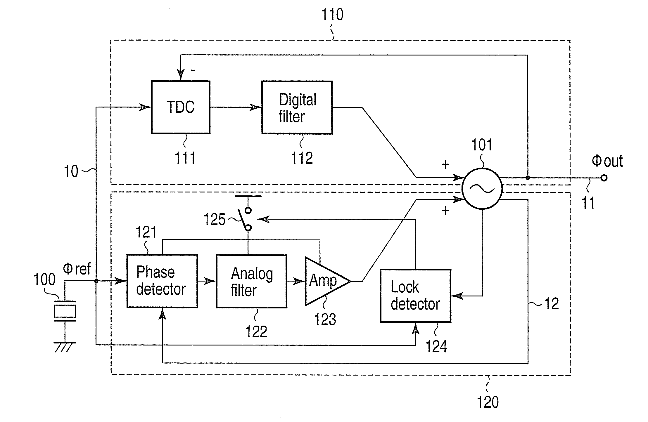
[0054]As FIG. 1 shows, a phase synchronization circuit according to a first embodiment of the invention has a reference signal generator 100, a controlled oscillator 101, a TDC 111, a digital filter 112, a phase detector 121, an analog filter 122, an amplifier 123, a lock detector 124, and a switch 125.

[0055]In the phase synchronization circuit of FIG. 1, the controlled oscillator 101, TDC 111 and digital filter 112 constitute a digital loop 110. The controlled oscillator 101, phase detector 121, analog filter 122 and amplifier 123 constitute an analog loop 120. The digital loop 110 locks the frequency and phase of the output signal of the controlled oscillator 101 to the frequency and phase of the reference signal generated by the reference signal generator 100. Then the analog loop 120 suppresses the phase noise generated in the controlled oscillator 101.

[0056]The reference signal generator 100 is, for example, a crystal oscillator, and generates a reference signal 10. The referen...

second embodiment

[0098]As seen from FIG. 14, a phase synchronization circuit according to a second embodiment of this invention differs from the circuit of FIG. 1, in that a VCO 201 and a digital loop 210 replace the controlled oscillator 101 and the digital loop 110, respectively. In FIG. 14, the components identical to those shown in FIG. 1 are designated by the same reference numbers. The components characterizing the second embodiment will be described in the main.

[0099]In the digital loop 210 that corresponds to the digital loop 110 shown in FIG. 1, a digital-to-analog converter (DAC) 213 is connected to the output of the digital filter 112. The DAC 213 receives a digital output signal from the digital filter 112 and converts the same to an analog signal. The analog signal is input, as the first signal, to the VCO 201.

[0100]The VCO 201 is constituted by a ring oscillator comprising a plurality of inverting amplifiers that are circularly connected in cascade. The VCO 201 receives the first contr...

third embodiment

[0102]As seen from FIG. 15, a phase synchronization circuit according to a third embodiment of this invention differs from the circuit of FIG. 1, in that a controlled oscillator 301, a differential to single-phase converter 302 and a phase shifter 303 replace the controlled oscillator 101. In FIG. 15, the components identical to those shown in FIG. 1 are designated by the same reference numbers. The components characterizing the third embodiment will be described in the main.

[0103]The controlled oscillator 301 is an LC oscillator that includes variable capacitors and generates less noise than the VCO 201 described above. In the controlled oscillator 301, the first control signal input from the digital filter 112 to the first control terminal discretely controls the variable capacitors in terms of capacitance. The second control signal input from the amplifier 123 to the second control terminal also controls capacitances of the variable capacitors. Thus, the controlled oscillator 301...


PUM


Abstract

A phase synchronization circuit includes a controlled oscillator configured to generate a first oscillation signal and a second oscillation signal that have a common frequency but different phase controlled by a combination of a first control signal and a second control signal, a digital phase frequency detector configured to detect a frequency difference and a first phase difference between a reference signal and the first oscillation signal to generate the first control signal, an analog phase detector configured to detect a second phase difference between the second oscillation signal and the reference signal to generate the second control signal, and a lock detection unit configured to detect a lock of the first oscillation signal with the reference signal in terms of frequency and phase, in order to set the analog phase detector in an active state.

Description

CROSS-REFERENCE TO RELATED APPLICATIONS[0001]This application is based upon and claims the benefit of priority from prior Japanese Patent Application No. 2008-032821, filed Feb. 14, 2008, the entire contents of which are incorporated herein by reference.BACKGROUND OF THE INVENTION[0002]1. Field of the Invention[0003]The present invention relates to a phase synchronization circuit that generates an output signal synchronous with a reference signal in both frequency and phase, and to a receiver that incorporates this phase synchronization circuit.[0004]2. Description of the Related Art[0005]Phase synchronization circuits that can generate an output signal synchronous with a reference signal in frequency and phase are well known as phase locked loops (PLLs). An exemplary PLL includes a voltage-controlled oscillator (VCO), a phase detector, an analog filter, and an amplifier. The VCO has its oscillation frequency controlled by the control voltage applied to it. The phase detector detect...

Claims


Application Information

Patent Timeline
IPC IPC(8): H04L7/00H03L7/06
CPCH03L7/087H03L7/0891H03L7/095H03L2207/18H03L7/10H03L2207/06H03L7/0995H03L7/107H03L7/101
Inventor SAI, AKIHIDE
Owner KK TOSHIBA
Why Eureka
Try Eureka