Hollow fiber and method for fabricating same
a technology of hollow fiber and hollow fiber, which is applied in the field of hollow fiber, can solve the problems of reducing the breakdown threshold of hollow fiber, difficult to provide silver iodide thin film with a smooth surface and uniform film thickness along the longitudinal direction, and improving the transmission of high-power laser light. , the effect of superior stability
- Summary
- Abstract
- Description
- Claims
- Application Information
AI Technical Summary
Benefits of technology
Problems solved by technology
Method used
Image

Examples
first preferred embodiment
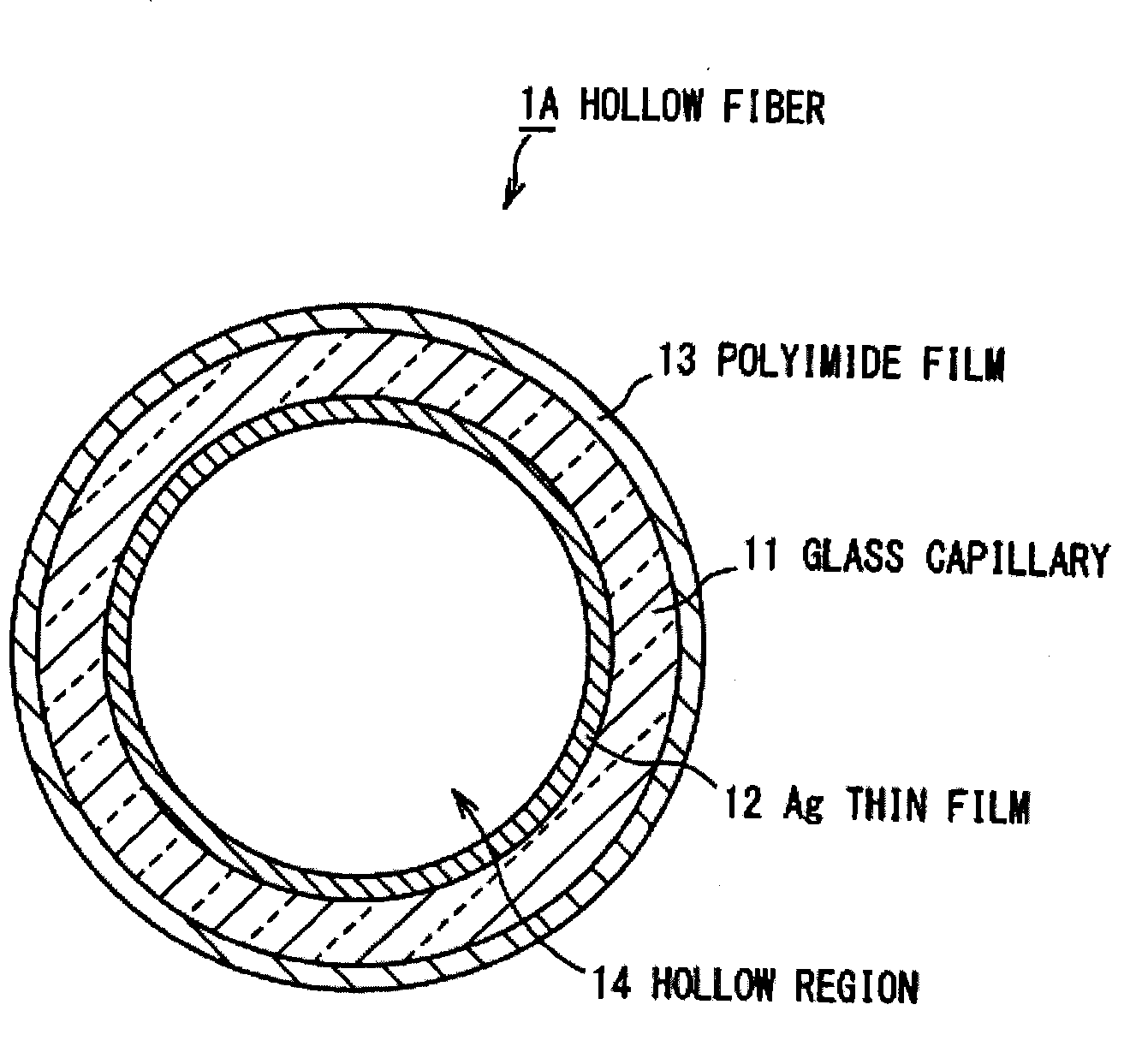
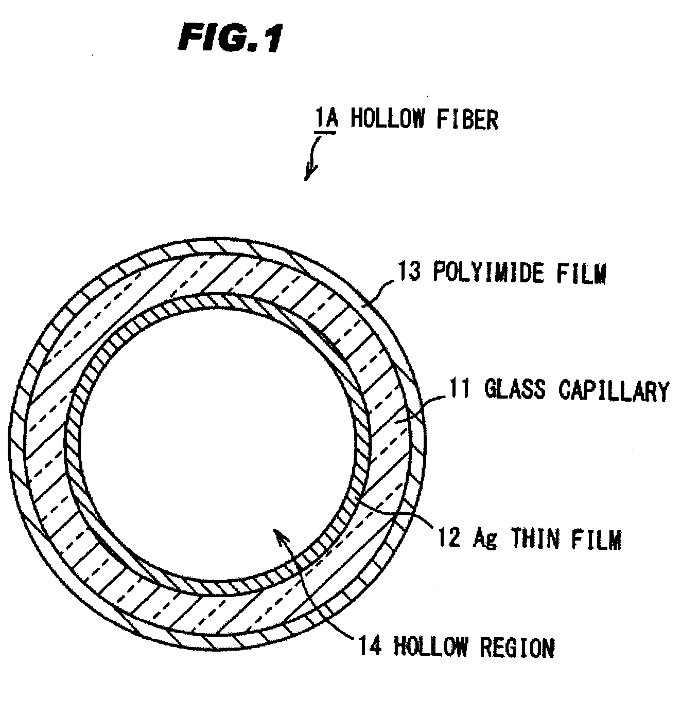
[0066]FIG. 1 is a cross sectional view of a hollow fiber in a first preferred embodiment according to the present invention.
[0067]A hollow fiber 1 comprises a hollow shaped glass capillary 11 comprising a quartz (silica), a silver (Ag) thin film 12 as a reflecting film formed by baking silver (Ag) nano particles inside the hollow-shaped glass capillary 11, and a polyimide film 13 coated to cover an outer periphery surface of the glass capillary 11. This hollow fiber 1 is configured to propagate a light in a hollow region 14 provided at an inner surface of the Ag thin film 12.
[0068]The glass capillary 11 is formed to have an inner wall with a smooth surface, and is superior in optical characteristics and heat resistance. In the first preferred embodiment, a quartz glass capillary having an inner diameter of 500 μm and an outer diameter of 650 μm is used, and this quartz glass capillary is also superior in flexibility.
[0069]It is preferable that the Ag thin film 12 has an average part...
second preferred embodiment
[0089]FIG. 3 is a schematic diagram showing a fabrication apparatus of a hollow fiber in a second preferred embodiment according to the present invention.
[0090]In FIG. 3, partial longitudinal sectional views of the syringe 20 and the glass capillary 11 are shown to facilitate the explanation of the invention. Further, in following explanation, similar reference numerals are assigned to parts having structure and function similar to those in the first preferred embodiment.
[0091]The fabrication apparatus of the hollow fiber in the second preferred embodiment is configured to provide a branch pipe 36 for injecting the Ag nano particle solution 40 into plural glass capillaries 11 between the syringe 20 and the glass capillary 11 in the first preferred embodiment.
[0092]The branch pipe 36 is such configured that the syringe 20 is connected to a cap 36A at an inlet end thereof and connected to a cap 31A of each of the glass capillaries 11 at each of outlet ends thereof, and that the nano p...
third preferred embodiment
[0094]FIG. 4 is a schematic diagram showing a fabrication apparatus of a hollow fiber in a third preferred embodiment according to the present invention.
[0095]In FIG. 4, partial longitudinal sectional views of a vessel 26 and the waste liquid vessel 24 are shown to facilitate the explanation of the invention.
[0096]The fabrication apparatus of a hollow fiber in the third preferred embodiment is such configured that a tubular vessel 26 accommodating the Ag nano particle solution 40 is connected to a cap 31A at an inlet end (upper side) of the glass capillary 11, and that a piping 27 having an elasticity is connected to a cap 31B at an outlet end (lower side). The piping 27 is provided with a peristaltic pump 28, and a terminal of the piping 27 provided at a downstream side with respect to the peristaltic pump 28 is located to be inside of the waste liquid vessel 24.
[0097]The peristaltic pump 28 applies an external force to the piping 27 with a roller or the like to contract the piping...
PUM
| Property | Measurement | Unit |
|---|---|---|
| particle diameter | aaaaa | aaaaa |
| viscosity | aaaaa | aaaaa |
| temperature | aaaaa | aaaaa |
Abstract
Description
Claims
Application Information
 - Generate Ideas
- Intellectual Property
- Life Sciences
- Materials
- Tech Scout
- Unparalleled Data Quality
- Higher Quality Content
- 60% Fewer Hallucinations
Browse by: Latest US Patents, China's latest patents, Technical Efficacy Thesaurus, Application Domain, Technology Topic, Popular Technical Reports.
© 2025 PatSnap. All rights reserved.Legal|Privacy policy|Modern Slavery Act Transparency Statement|Sitemap|About US| Contact US: help@patsnap.com