Air-fired co2 capture ready circulating fluidized bed steam generators

a fluidized bed and air-fired technology, applied in the field of air-fired fluidized bed steam generators, can solve the problems of reducing the capacity of the coal fired cfb boiler site, and reducing the service life of the cfb boiler

Active Publication Date: 2009-08-27
GENERAL ELECTRIC TECH GMBH
View PDF6 Cites 7 Cited by
  • Summary
  • Abstract
  • Description
  • Claims
  • Application Information

AI Technical Summary

Benefits of technology

[0018]According to another aspect of the present invention, if, but only if, such combustion of the fossil fuel is performed while the steam generating system is being operated in an oxygen fired mode and the hot solids have been separated from the flue gas that is generated from the combustion of the fossil fuel, heat preferably is then transferred from the hot solids that have been separated from the flue gas to another working fluid, which without departing from the essence of the present invention could be either a second, or a third or a fourth working fluid depending on the nature of the particular application in which the present invention is being employed, in order to thereby effect a cooling therewith of the hot solids that have been separated from the flue gas and concomitantly therewith a heating of the latter working fluid. Preferably, the hot solids that are being subjected to cooling are fluidized with recycled flue gas, and such fluidized cooled solids are then subjected to combustion in order to thereby effect therewith a heating of the first working fluid and the flue gas that is generated from such combustion. In this case also, the latter working fluid without departing from the essence of the present invention could be in the form of water, steam, a mixture of water and steam, or some other type of working fluid. This latter heated working fluid as well as one or both of the other two heated working fluids to which reference has been had hereinbefore, are all suitable for purposes of being employed to drive the turbine.
[0019]In accordance with an application thereof by way of exemplification, a steam generating system constructed in accordance with the present invention includes a fossil fuel fired circulating fluidized bed (CFB) boiler, an air preheater, and a blower, the latter sometimes being referred to herein as a first blower. To this end, such a fossil fuel fired circulating fluidized bed (CFB) boiler is suitably configured, i.e., is suitably sized, suitably shaped and/or incorporates the necessary components, both to effect fluidization of such fossil fuel in order to thereby create therewith a fluidized bed, and to effect the combustion of such fossil fuel in order to effect a heating of a first working fluid and concomitantly therewith the generation of a flue gas. Continuing, such a fossil fuel fired circulating fluidized bed (CFB) boiler is also suitably configured so as to be capable of effecting therewith the exhaust of a flow of the heated first working fluid as well as a flow of the flue gas. With further regard to the aforedescribed exemplary application, the air preheater thereof preferably is configured so as to capable of receiving the flue gas that is exhausted from the fossil fuel fired circulating fluidized bed (CFB) boiler.
[0020]When the steam generating system to which reference is made in the preceding paragraph is being operated in an air fired mode, the blower thereof is suitably configured so as to be operative to cause air to be forced to the air preheater. The air preheater in turn is then operative to cause heat from the flue gas that is received by the air preheater to be transferred to the air, which flows through the air preheater, in order to thereby effect a preheating of such air. The air that is so preheated in the air preheater is then made to flow from the air preheater to the fossil fuel fired circulating fluidized bed (CFB) boiler and is employed in the latter for purposes of effecting therewith a fluidization of the fossil fuel. On the other hand, when the steam generating system to which reference is made in the preceding paragraph is being operated in an oxygen fired mode, the blower thereof is suitably configured so as to be operative to cause both oxygen and recycled flue gas to be forced to flow to the air preheater. The air preheater in turn is then operative to cause heat from the flue gas that is received by the air preheater to be transferred to such oxygen and recycled flue gas, in order to thereby effect therewith a preheating of such oxygen and recycled flue gas and concomitantly therewith a cooling of the flue gas that is received by the air preheater. The oxygen and recycled flue gas that is so preheated in the air preheater is then made to flow from the air preheater to the fossil fuel fired circulating fluidized bed (CFB) boiler and is employed in the latter for purposes of effecting a fluidization of the fossil fuel.
[0021]Typically, the combustion of the fossil fuel in the fossil fuel fired circulating fluidized bed (CFB) boiler also operates to generate residual hot solids, which become entrained in the hot flue gas that is exhausted from the fossil fuel fired circulating fluidized bed (CFB) boiler. If this is the case, the steam generating system constructed in accordance with the present invention preferably also includes a separator, and a heat exchanger, and another, i.e., a second, blower. Continuing, such a separator is designed to be configured so as to be operative to effect therewith a separation of such hot solids that are entrained in the hot flue gas from the hot flue gas that is exhausted from the fossil fuel fired circulating fluidized bed (CFB) boiler. It is this flue gas from which the hot solids have been separated that is received by the air preheater as has been described hereinabove. Continuing, the heat exchanger to which reference is made above, which sometimes will be referred to herein as a first heat exchanger, is designed so as to be suitably configured in order to be operative to receive the hot solids, which have

Problems solved by technology

However, while the technique that is disclosed and illustrated in U.S. Pat. No. 6,505,567 can be used for purposes of significantly reducing the amount of CO2 emissions, there nevertheless remains a reluctance by some in many quarters to provide additional coal fired steam generating system capacity because of their concerns that there may be enacted future governmental regulations regarding CO2 emissions and the costs that may be required to be incurred in order to thereby meet such regulations.
With further reference thereto, particularly in the case of retrofit situations, the site itself of such coal fired CFB boiler steam generating systems may be insufficient to accommodate a CF

Method used


Image

  • Air-fired co2 capture ready circulating fluidized bed steam generators
  • Air-fired co2 capture ready circulating fluidized bed steam generators
  • Air-fired co2 capture ready circulating fluidized bed steam generators

Examples


first embodiment

Dual Mode System Components and Operations

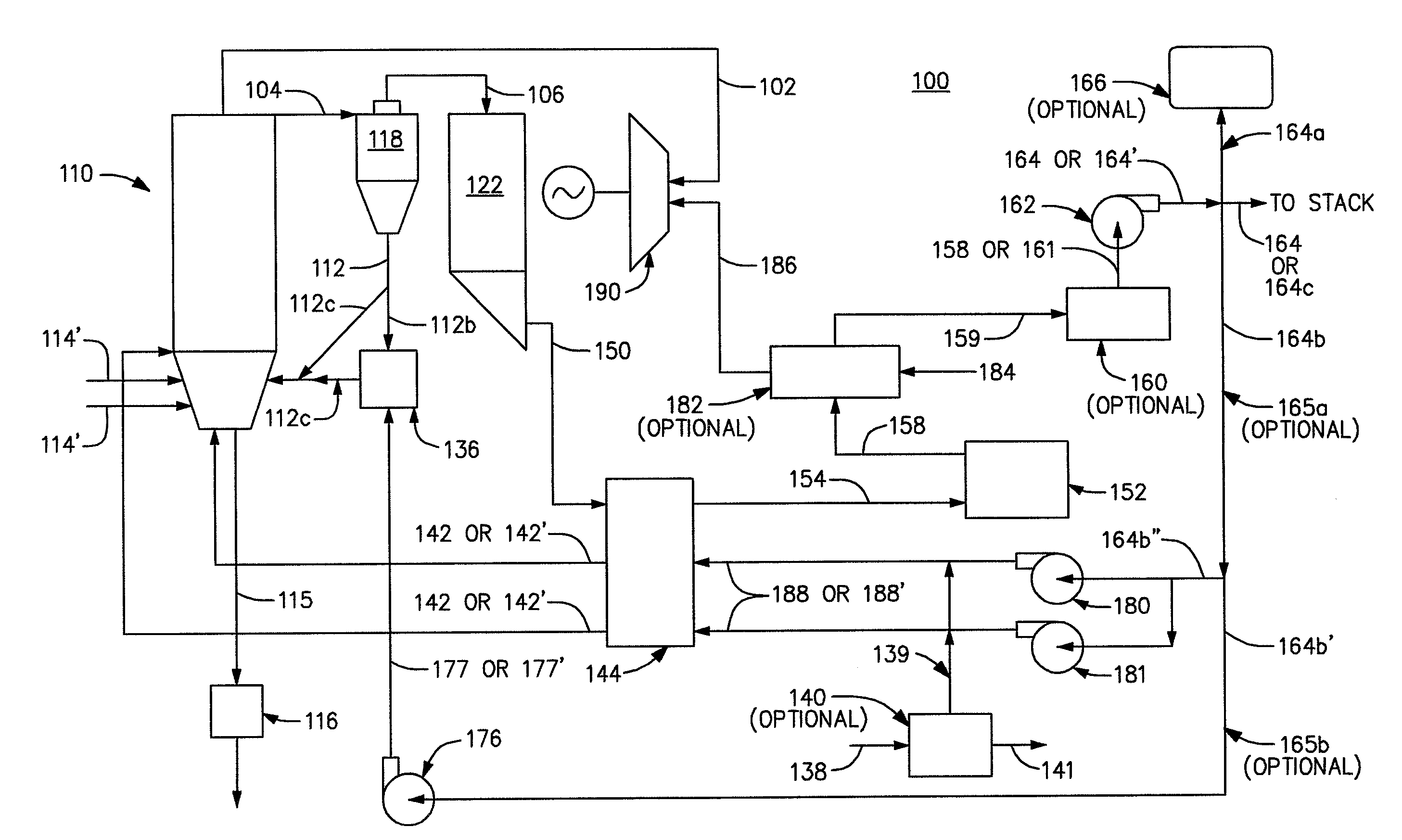
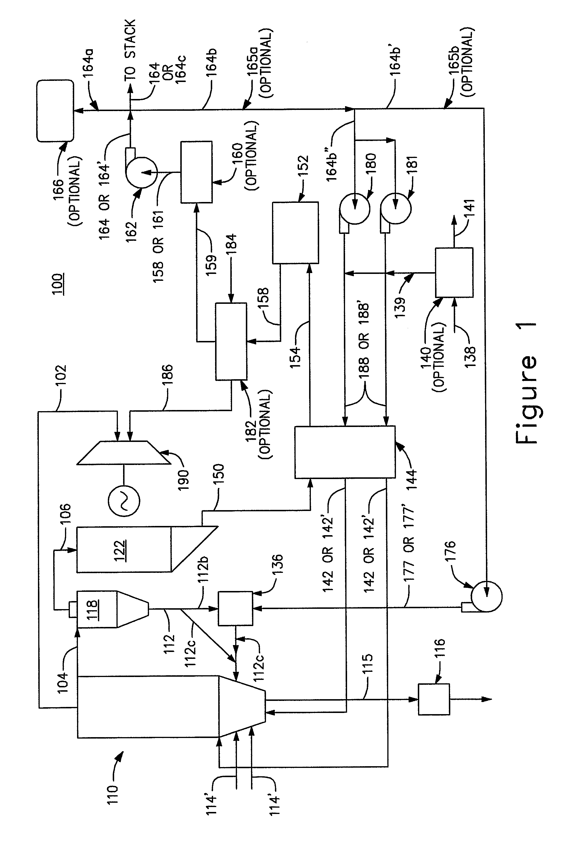
[0026]In FIG. 1 there is depicted by way of exemplification a schematic illustration of an exemplary air or oxygen (O2) fired circulating fluidized bed (CFB) steam generating system 100, constructed in accordance with a first embodiment of the present invention. The circulating fluidized bed (CFB) steam generating system 100, employs air, or when equipped with certain optional components is capable of being operated such as to employ O2 in lieu of air, in order to thereby effect therewith the combustion of fossil fuel.

[0027]In accordance with the mode of operation thereof that is described hereinbelow, the fossil fuel that is combusted in the circulating fluidized bed (CFB) steam generating system 100 preferably is crushed coal. It should be understood that other types of fossil fuels could equally well be utilized in lieu of crushed coal without departing from the essence of the present invention. However, in any event preferably a fossil f...

second embodiment

Dual Mode System Components and Operations

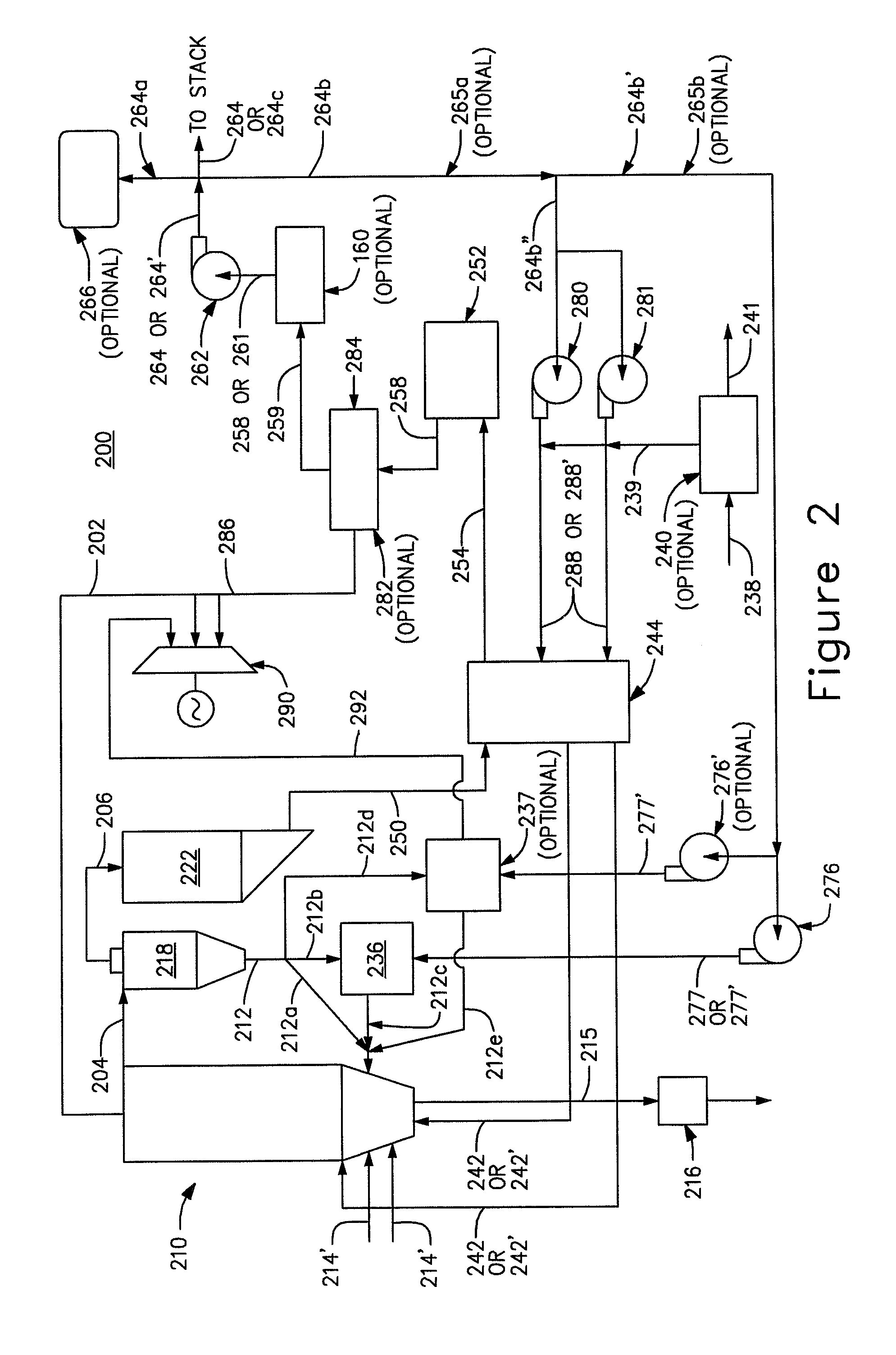
[0060]In FIG. 2 there is illustrated a schematic view of an exemplary air fired or oxygen (O2) fired steam generating system 200, constructed in accordance with a second embodiment of the present invention. The steam generating system 200, is capable of using air, or when fitted with selected optional components is capable of using O2 in lieu of air, for purposes of effecting therewith the combustion of fossil fuel.

[0061]In the particular exemplary application of the present invention that is described below, the fossil fuel that is employed therewith is crushed coal. It should be understood, however, that without departing from the essence of the present invention other types of fossil fuels could equally well be utilized in lieu of such crushed coal. To this end, preferably a fossil fuel having a high carbon content such as crushed coal or petcoke, or a biomass is employed in this regard. Continuing, the working fluid that is employed ther...


PUM


Abstract

A combustor 110 is operative to effect therewith the combustion of fossil fuel 114′ in order to thereby both heat to a working fluid 102 and generate a flue gas 104. An air preheater 144 receives the flue gas 104 generated in the combustor 110. A blower 180 causes air 188 to flow to the air preheater 144 when operating in an air fired mode, and causes both O2 and recycled flue gas 188′ to flow when operating in the O2 firing mode. The air preheater 144 is operative to transfer heat from the flue gas 150 received thereby to the air 188 that is received when operating in an air fired mode or to both the received O2 and the recycled flue gas 188′ that is received when operating in the O2 firing mode in order to thereby effect a preheating of the air 188 or of both the O2 and recycled flue gas, 188′ depending upon the specific nature of the mode of operation thereof, and to thereby effect therewith a cooling of the flue gas received thereby. The preheated air 142 or both the preheated O2 and the recycled flue gas 142′, depending upon the specific nature of the mode of operation, is caused to flow from the air preheater 144 to the combustor 110 in order to thereby effect therewith a fluidization of the fossil fuel 114′.

Description

CROSS-REFERENCE TO RELATED APPLICATION[0001]The present invention claims the benefit of co-pending U.S. Provisional Patent Application Ser. No. 61 / 031,764, entitled “AIR-FIRED CO2 CAPTURE READY CIRCULATING FLUIDIZED BED HEAT GENERATION”, and co-pending U.S. Provisional Patent Application Ser. No. 61 / 031,761, entitled “AIR-FIRED CO2 CAPTURE READY CIRCULATING FLUIDIZED BED HEAT GENERATION WITH A REACTOR SUBSYSTEM”, both of which are incorporated herein by reference in their entirety.FIELD OF THE INVENTION[0002]The present invention relates generally to steam generation, and more particularly, to air-fired fluidized bed steam generators that are CO2 capture ready in that such fluidized bed steam generators are retrofitable for oxygen firing.BACKGROUND OF THE INVENTION[0003]Heat generating systems embodying furnaces for combusting fossil fuels have long been utilized to generate controlled heat, with the objective of doing useful work. The work might be in the form of direct work, as wi...

Claims


Application Information

Patent Timeline
IPC IPC(8): F23J15/00F23C10/00F22B31/00F23J15/06F23J99/00F23L7/00F22B31/08F23C7/06
CPCF22B31/0007F23C9/00F23C10/10F23J15/006F23J15/06F23J2215/50Y02E20/348F23L15/04F23L2900/07001F23L2900/07003F23L2900/15042Y02E20/322Y02E20/344F23L7/007Y02E20/32Y02E20/34
Inventor ANDRUS, JR., HERBERT E.LILJEDAHL, GREGORY N.MARION, JOHN L.NSAKALA, NSAKALA YA
Owner GENERAL ELECTRIC TECH GMBH
Why Eureka
Try Eureka