[0014]The shape of the wall surface of the second inner wall part contacting with the conductor layer is not particularly limited, but includes, for instance, a flat surface, a
concave surface, a convex surface and a convexo-
concave surface. It is preferable that among these surfaces, at least one part of the wall surface in the portion contacting with the conductor layer in the second inner wall part has a concave shape. The second inner wall part inclines at a predetermined taper angle. At this time, when at least one part of the wall surface in a portion contacting with the conductor layer in the second inner wall part has a concave shape (in other words,
concave surface), the above described portion retains an increased amount of a plated film thereon, and makes the plated film easily and further sufficiently thick, which is advantageous.
[0015]A method for manufacturing a printed wiring board according to the present invention is a process of effectively manufacturing the printed wiring board according to the present invention, and is a method for manufacturing a printed wiring board in which a conductor layer provided on one side (face) of the insulation layer is electrically connected with a wiring layer provided on other side (face) of the insulation layer via a through hole formed on the insulation layer, including the steps of: forming a conductor layer having an aperture on the insulation layer; forming a hole having a smaller size than that of the aperture (hole having dimension included within region of aperture) in a portion corresponding to the aperture in the insulation layer; forming a through hole for connecting the conductor layer with the wiring layer in a portion corresponding to the hole in the insulation layer while using the conductor layer having the aperture as a
mask; and forming a plated film in the inner part of the through hole and on the conductor layer to electrically connect the conductor layer with the wiring layer (plating in the inner part of the through hole and on the conductor layer to electrically connect the conductor layer with the wiring layer).
[0020]In addition, in the step of forming the through hole, it is preferable to
grind the insulation layer at a smaller
grinding rate than a
grinding rate (ground amount of insulation layer per unit time) for the insulation layer when forming the hole in a step of forming the hole and thereby form the through hole. By doing this, the edge of aperture is chamfered so that a taper face is formed in a portion including the open end of the hole (edge of aperture), so that the second inner wall part of the through hole is more easily formed.
[0021]In this case, more specifically, it is preferable to form the hole by
irradiation with a
laser in a step of forming the hole in the insulation layer, and to form the through hole with blast treatment (of any of wet type and dry type) in a step of forming the through hole in the insulation layer. By doing this, a portion having a fine and steep wall shape corresponding to the first inner wall part of the through hole can be easily formed only by
irradiation with a
laser, or by complex treatment of
irradiation with a laser and blast treatment. In addition, the edge of the aperture is chamfered so that a taper face can be formed in a portion including the open end of the hole (edge of aperture), because a
grinding rate by the blast treatment for the insulation layer is generally smaller than that by the laser irradiation. Accordingly, the blast treatment makes the second inner wall part remarkably and more surely formed in the through hole.
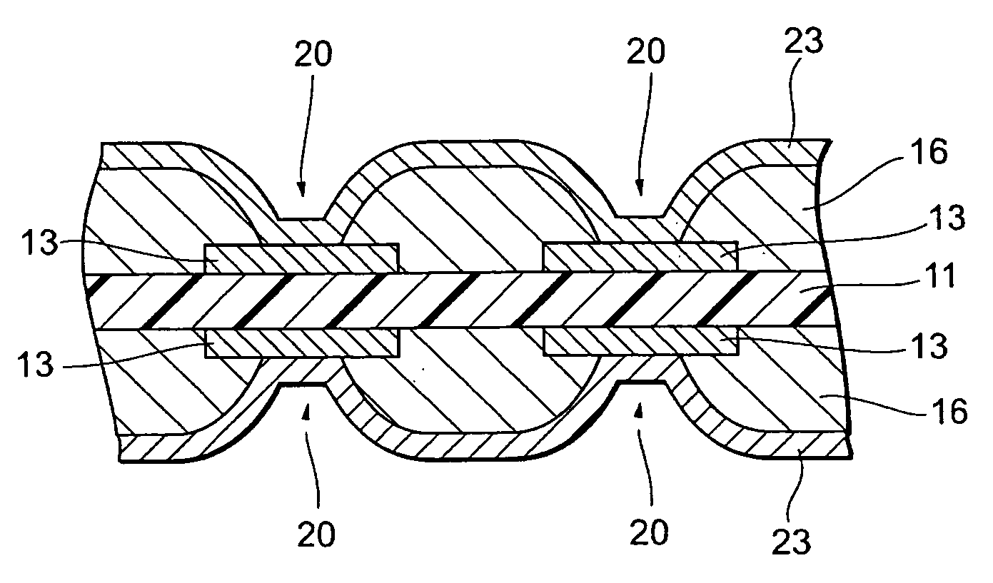
[0023]In a printed wiring board and the manufacturing method therefor according to the present invention, a conductor layer is connected with a wiring layer via a through hole which has been pierced in an insulation layer, and the through hole has a first inner wall part having a relatively small taper angle and a second inner wall part having a relatively large taper angle. Thereby, when the wiring layer and the inner part of the through hole are plated, the plated film in a portion contacting at least with the conductor layer in the periphery of the opening of the through hole is formed sufficiently thicker than that in the portion of a conventional through hole which does not have the second inner wall part. Thus, the manufacturing method can prevent the plated film from being locally thinned, accordingly can enhance the reliability of the connection between the wiring layer and the conductor layer, even though a via has a higher
aspect ratio than that in the conventional film, further can previously set the whole plated film thickness at a small value, consequently, can sufficiently cope with the trend of finer pitches and by extension of higher density packaging, and can further enhance the product reliability.

