Pixel circuit, electro-optical device of digital driving type, and electronic apparatus

a technology of electrooptical devices and electronic devices, applied in static indicating devices, instruments, photoelectric discharge tubes, etc., can solve problems such as easy generation of non-uniform display, easy generation of maintained voltage, and easy change of maintained voltage caused by leak current, so as to improve display quality of small-size electronic devices, high accuracy, and high reliability

Active Publication Date: 2009-08-27
SEIKO EPSON CORP
View PDF1 Cites 5 Cited by
  • Summary
  • Abstract
  • Description
  • Claims
  • Application Information

AI Technical Summary

Benefits of technology

[0010]An advantage of some aspects of the invention is that it provides a highly reliable pixel circuit, which is appropriate for a digital driving type, having a small number of elements, occupying a small area, and capable of writing data with high accuracy and maintaining the written voltage.

Problems solved by technology

In the analog driving type, non-uniformity of display can be easily generated due to the non-uniformity of characteristics of elements (a D / A converter, an operational amplifier, a wiring, and the like) configuring the circuit.
However, in the DRAM-type pixel circuit, a change (for example, see JP-A-5-224235) in the maintained voltage caused by feed-through or a change in the maintained voltage caused by a leak current can easily occur.
However, in such a case, the circuit configuration is complicated.
Accordingly, an increase in the size of the pixel circuit and an increase in the power consumption of the pixel circuit are inevitable.
In the liquid crystal display device of the digital driving type, when a RAM-type pixel circuit is used, the circuit configuration is complicated, and thereby an increase in the size of the pixel circuit and an increase in the power consumption of the pixel circuit occur.
Accordingly, it is difficult to implement high-definition image display while miniaturization and low power consumption of the liquid crystal display device are achieved.
Accordingly, in such a case, the electric potential of the holding node is inverted, and incorrect data is maintained.
However, generally, a pixel circuit of a display device may be periodically (regularly) rewritten for a predetermined period, and thus, a state in which the pixel circuit is not selected for a long time, and the voltage of the holding node markedly changes due to the off-leak current of the feedback transistor during the time cannot occur easily.
However, for example, in a case where the voltage of the holding node changes quite markedly due to the feed-through, when the output voltage of the inverter is inverted incorrectly, miss-latch of data (data is written incorrectly) occurs.

Method used


Image

  • Pixel circuit, electro-optical device of digital driving type, and electronic apparatus
  • Pixel circuit, electro-optical device of digital driving type, and electronic apparatus
  • Pixel circuit, electro-optical device of digital driving type, and electronic apparatus

Examples


first embodiment

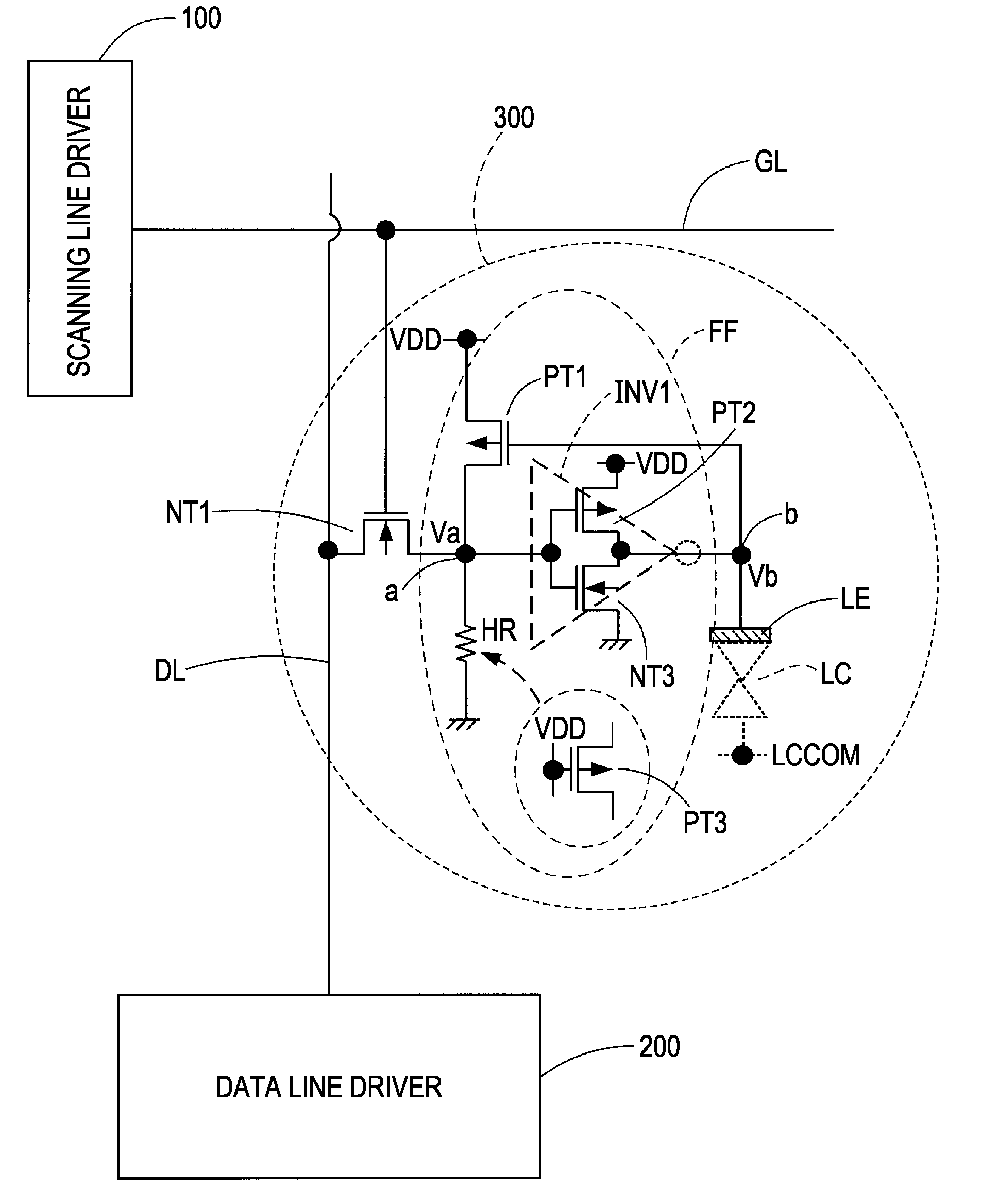
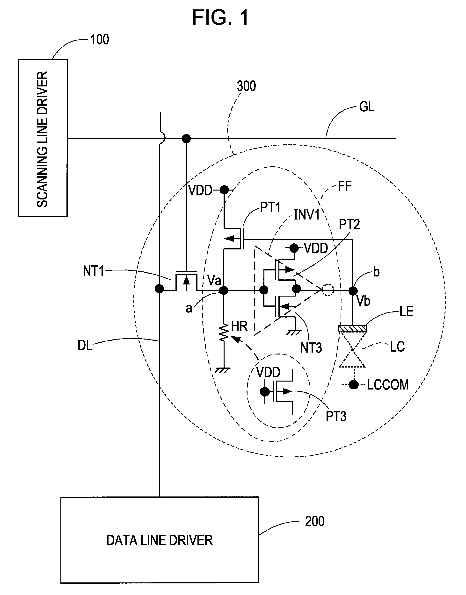
[0056]FIG. 1 is a circuit diagram showing an example of the configuration of a pixel circuit according to an embodiment of the invention. As shown in the figure, the pixel circuit 300 is disposed in correspondence with an intersection of a scanning line GL and a data line DL. The scanning line GL is driven by a scanning line driver 100, and the data line DL is driven by a data line driver 200.

[0057]The pixel circuit 300, for example, includes a pixel transistor NT1 that is formed by an NMOS transistor (n-channel insulated gate-type field effect transistor regardless of the type of an insulation film), a flip-flop FF, and a pixel electrode LE (electrode for applying a voltage to a liquid crystal LC).

[0058]The flip-flop FF includes a CMOS inverter INV1 that operates between the high-level power source voltage VDD and the low-level power source voltage GND and a feedback transistor PT1 that is formed of a PMOS transistor. The CMOS inverter INV1 and the feedback transistor PT1 form a po...

second embodiment

[0077]In a second embodiment of the invention, a countermeasure for a change in the writing voltage due to the feed-through voltage of the pixel transistor will be described. FIGS. 4A to 4C are diagrams for describing adjustment of the threshold voltage of the CMOS inverter as a countermeasure for the change in the writing voltage due to the feed-through voltage of the pixel transistor.

[0078]In FIG. 4A, it is assumed that “1” is written into the pixel circuit. When a writing operation is completed and the voltage of the scanning line GL changes from H to L, a push-down voltage (feed-through voltage: −ΔV) is generated due to parasitic capacitance Cgd between the gate and drain of the pixel transistor (NMOS transistor) NT1. Accordingly, the electric potential of point “a” becomes (VDD−ΔV). FIG. 4C shows transfer characteristics of the CMOS inverter INV1. As denoted by a dotted line in FIG. 4C, for example, in a case where the threshold voltage is set to VDD / 2, when the absolute value ...

third embodiment

[0081]FIGS. 5A and 5B are diagrams showing an improved example for a case where data “0” is written into the pixel circuit that maintains data “1”.

[0082]As shown in FIG. 5A, data “1” (=VDD) is maintained at the holding node (point a) of the pixel circuit. In this state, as shown in FIG. 5B, a case where data “0” (=GND) is written into the pixel circuit will be considered.

[0083]In this case, when the scanning line GL has a selection electric potential (H), the pixel transistor NT1 is turned on. Accordingly, an on-current Ionn1 flows from the holding node (point a) to the data line DL. When the on-current Ionn1 of the pixel transistor NT1 is larger than the on-current Ionp1 of the feedback transistor PT1, the voltage level of the holding node (point a) transits from the H level to the L level. Accordingly, data “0” can be written.

[0084]Thus, in order to perform a writing operation assuredly, the characteristics (design values such as the sizes) of the pixel transistor NT1 and the feed...


PUM


Abstract

There is provided a pixel circuit that is disposed in correspondence with an intersection of a scanning line and a data line. The pixel circuit includes a pixel electrode, a pixel transistor of a first conduction type that has a control node connected to the scanning line, a first node to which the data line is connected, and a second node, and a flip-flop that is disposed between the second node of the pixel transistor and the pixel electrode. The flip-flop has an inverter having an input node connected to the second node of the pixel transistor and an output node connected to the pixel electrode and a feedback transistor of a second conduction type, which is a conduction type opposite to the first conduction type, that is controlled to be turned on or off in accordance with an output of the inverter and supplies a high-level power source voltage or a low-level power source voltage to a common connection point of the second node of the pixel transistor and the input node of the inverter, in the ON state.

Description

BACKGROUND[0001]1. Technical Field[0002]The present invention relates to a pixel circuit, an electro-optical device of a digital driving type (for example, a liquid crystal display device employing a subfield driving type), and an electronic apparatus.[0003]2. Related Art[0004]For example, as a driving method for a liquid crystal display device, there are an analog driving type (a method in which an analog voltage corresponding to a display gray scale is applied to a data line) and a digital driving type (a driving method in which there are only two values including an ON level and an OFF level as voltage levels needed for driving a pixel). In the analog driving type, non-uniformity of display can be easily generated due to the non-uniformity of characteristics of elements (a D / A converter, an operational amplifier, a wiring, and the like) configuring the circuit. On the other hand, in the digital driving type, used driving voltages (writing voltages for a pixel) are binary, and acc...

Claims


Application Information

Patent Timeline
Patent Type & Authority Applications(United States)
IPC IPC(8): H01J40/14
CPCG02F2001/136245G09G2300/0857G09G3/3648G02F1/136245
Inventor WATANABE, KENYAISHII, RYO
Owner SEIKO EPSON CORP
Why Eureka
Try Eureka