Metallic Nanostructures Adapted for Electromagnetic Field Enhancement

a nano-structure and electromagnetic field technology, applied in the field of nanostructures, can solve the problems of difficult control of particle distance and difficult to fabricate consistently

Active Publication Date: 2009-08-27
RGT UNIV OF CALIFORNIA
View PDF5 Cites 43 Cited by
  • Summary
  • Abstract
  • Description
  • Claims
  • Application Information

AI Technical Summary

Benefits of technology

[0008]The invention also provides a metallic nanostructure comprising a spherical, asymmetrical tapered metallic shell having a single round opening surrounded by an edge, wherein the nanostructure has an inner radius r and an outer radius R, wherein said outer radius R is greater than the inner radius r, and wherein the nanostructure has a greatest thickness opposite the opening, and wherein the edge has a thickness that is less than the greatest thickness.
[0009]The invention further provides a method for making a nanostructure of the invention. The method includes dispersing template nanostructures on a surface; depositing one or more metal materials onto the template nanostructure to form coated nanostructures; and removing the coated nanostructures from the surface, wherein the surface of the template nanostructure in contact with the surface comprises less metal material than any other part of the template nanostructure. In one embodiment, the method includes decomposing the template nanostructure.

Problems solved by technology

Conventional SERS substrates require multiple plasmonic couplings via many colloidal nanoparticles requiring particular coupling distances that are difficult to control in solution or biomolecular environments.
In conventional chemical synthesis or batch fabrications, the interparticle distance is difficult to control due to the stochastic distribution of the nanospheres on a substrate.
These structures provide significant field enhancement in experiments and in simulations but they have proved to be difficult to fabricate consistently.

Method used


Image

  • Metallic Nanostructures Adapted for Electromagnetic Field Enhancement
  • Metallic Nanostructures Adapted for Electromagnetic Field Enhancement
  • Metallic Nanostructures Adapted for Electromagnetic Field Enhancement

Examples


example 1

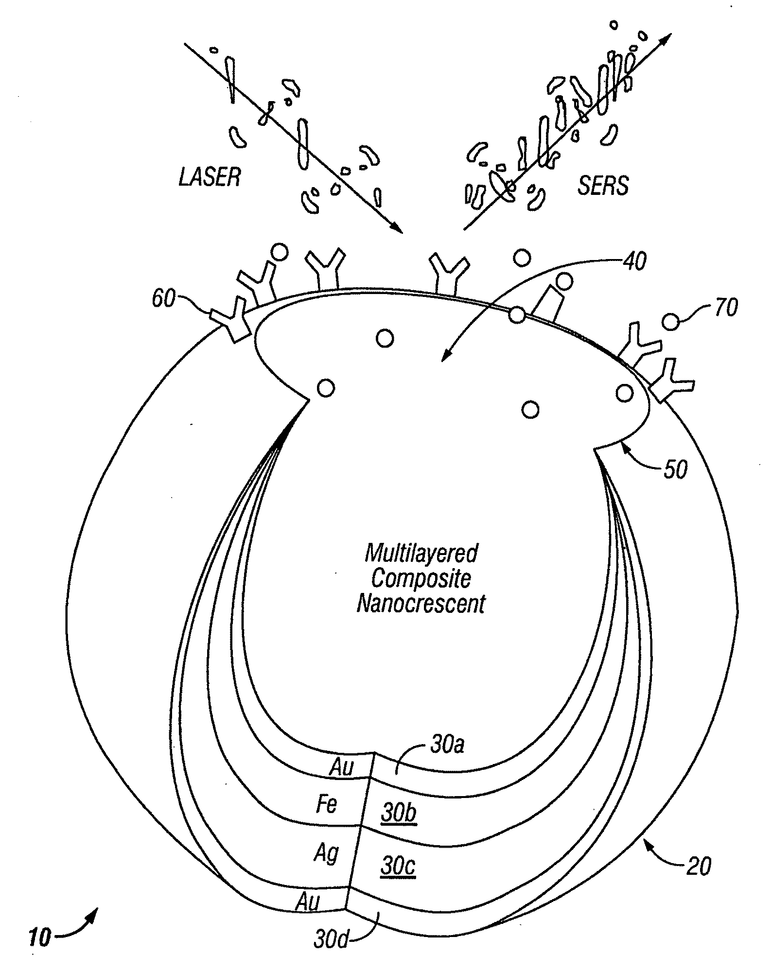
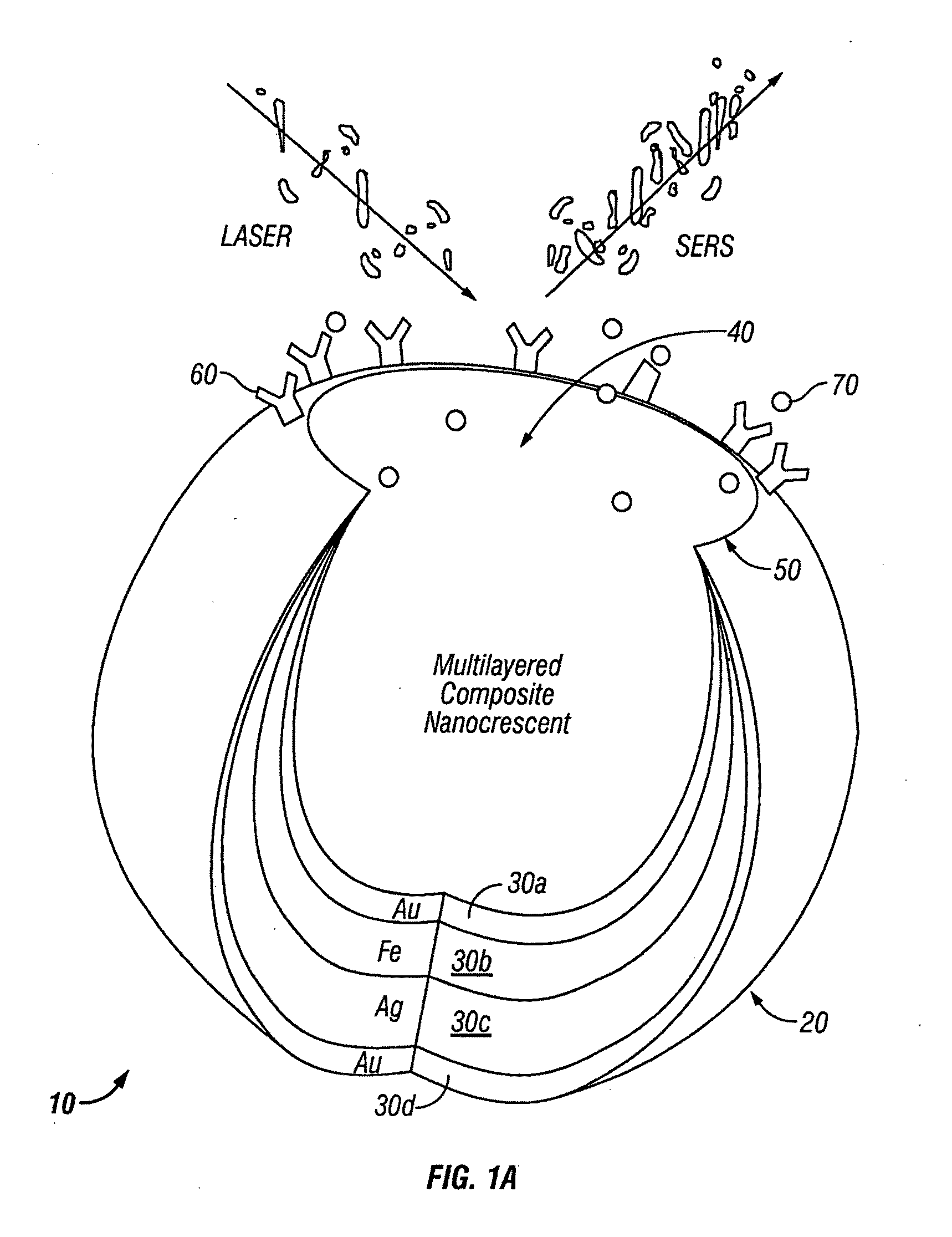
[0107]Fabrication of Nanocrescent SERS probes. The gold nanocrescent SERS probes are fabricated by rotational deposition of a thin gold layer on polymer nanospheres at certain angles and subsequent dissolution of the sacrificial nanosphere templates. The inner diameter and thickness of nanocrescent SERS probes can be controlled in the fabrication by choosing the size of sacrificial nanosphere templates as well as the gold deposition thickness and angle.

[0108]FIG. 2 shows the fabrication procedure, which depict a simple batch nanofabrication method. Glass slides were thoroughly rinsed with deionized water (Millipore, >18 MΩ) and dried under a stream of nitrogen gas. A thin layer of photoresist (Shipley S1818, Shipley, Mass.) was spin-coated on the cleaned glass substrates. Aqueous solutions of polystyrene colloids (300 nm; Duke Scientific, CA) were diluted in water to a volume fraction of 0.1%. A monolayer of sacrificial nanospheres was generated by drop-casting the dilute solution o...

example 2

[0129]In addition, the invention examines the ability of the nanostructures of the invention and related structures to include micro- and nano-fluidic movement. In an experiment to support this mechanism, a 2 μl water drop is dispensed on a hydrophobic glass slide, and a focused 785 nm laser beam with tunable power is used as the illumination source. The contact angle of the water drop on the glass slide was approximately 60° (other angles can be utilized). Approximately 1 nM PNPs were present in the liquid. When a 20 mW, 785 nm focused light spot was illuminated on the liquid contact line and translated outwards, the liquid evaporation, droplet formation and contact-line advance are clearly visible (FIG. 9b). The optically controlled advance of the liquid-air interface follows the light translation and stops on the removal of the illumination. However, as the liquid is unconfined in this case, the liquid flow cannot be guided unidirectionally and thus the flow speed is low.

[0130]In...


PUM


Abstract

The disclosure relates to metallic nanophotonic crescent structures, or “nanocrescent SERS probes,” that enhance detectable signals to facilitate molecular detections. More particularly, the nanocrescent SERS probes of the disclosure possess specialized geometries, including an edge surrounding the opening that is capable of enhancing local electromagnetic fields. Nanosystems utilizing such structures are particularly useful in the medical field for detecting rare molecular targets, biomolecular cellular imaging, and in molecular medicine.

Description

CROSS-REFERENCE TO RELATED APPLICATIONS[0001]This application claims priority under 35 U.S.C. §119 to U.S. Provisional Application Ser. No. 60 / 661,774, filed Mar. 14, 2005, the disclosure of which is incorporated herein by reference.STATEMENT REGARDING FEDERAL SPONSORED RESEARCH[0002]The U.S. Government has certain rights in this invention pursuant to Grant No. EEC-9813302 by the National Science Foundation.FIELD OF THE INVENTION[0003]The disclosure relates to nanostructures that enhance detectable signals to facilitate molecular detections and molecular imaging. More particularly, the nanostructures of the disclosure possess geometries capable of enhancing local electromagnetic fields. Nanosystems utilizing such structures are particularly useful in the medical field for detecting rare molecular targets, biomolecular cellular imaging, drug delivery and in molecular medicine.BACKGROUND[0004]Raman spectroscopy is a label-free technique desired for biomolecular detections and molecula...

Claims


Application Information

Patent Timeline
Patent Type & Authority Applications(United States)
IPC IPC(8): G01J3/44B05D7/00F21V9/04A61K33/24B01L3/00
CPCB82Y5/00B82Y15/00G01N21/658B82Y30/00B82Y40/00B82Y20/00
Inventor LEE, LUKE P.LU, YULIU, GANG L.KIM, JAEYOUN
Owner RGT UNIV OF CALIFORNIA
Why Eureka
Try Eureka