Integrated Fuel and Fuel Cell Device

a fuel cell and fuel cell technology, applied in the field of integrated fuel and fuel cell devices, can solve the problems of limited energy density, limited ability of current chemical batteries to operate under continuous load, and limited service life of rechargeable batteries,

Inactive Publication Date: 2009-08-27
H2VOLT
View PDF28 Cites 33 Cited by
  • Summary
  • Abstract
  • Description
  • Claims
  • Application Information

AI Technical Summary

Problems solved by technology

They have limited capacity in terms of energy density, whether that density is measured in terms of watt-hours per unit volume or watt-hours per unit mass of the device.
This capacity limitation impacts the ability of the current chemical battery to operate under continuous load.
Even rechargeable batteries are often limited to 4-5 hours of continuous usage.
They have a relatively short shelf-life, often less than 3 to 5 years.
Many modern batteries include harsh or toxic chemicals that pose long-term environmental hazards.
However, many fuel cell configurations have drawbacks of their own.
Although such fuel cells may be acceptable for providing electrical energy to stationary loads, these configurations are not currently considered appropriate for movable or portable loads, which may be found in consumer electronic devices.
Additionally, the very presence of an external fuel supply renders them impractical (perhaps, even, unsafe) for use in applications involving remote devices, such as safety devices or alarm sensors situated within a building structure.

Method used


Image

  • Integrated Fuel and Fuel Cell Device
  • Integrated Fuel and Fuel Cell Device
  • Integrated Fuel and Fuel Cell Device

Examples


example 1

[0118]An integrated fuel and fuel cell prototype device having a single fuel cell was constructed and tested. A fuel cell rated at 0.6V, obtained from Heliocentris Energie System GmbH (65×65×25 mm), was mounted on a housing made of machineable acrylic sheet. The dimensions of the integrated fuel and fuel cell prototype device were 65×65×85 mm. The fuel cell chamber was filled with 5 grams of NaBH4 powder and 0.01 g of a cobalt metal powder. Both materials were obtained from Alfa Chemical Corporation. The device included a 20 ml water reservoir separated from the solid fuel by an anionic membrane made by Sybron Chemicals. For this Example, the water reservoir was charged with 10 ml of water. An amount of at least about 500 μl water would be theoretically sufficient for initiating operation. The fuel cell open circuit potential was measured at 0.85 V. A small motorized fan was connected to the fuel cell. Under that load, the voltage was measured to be 0.6 V. In the first test of the d...

example 2

[0119]In example 2, a variation of the device described in Example 1 was made having a double membrane thickness, so that the water permeability varied from Example 1 and the water flux rate was reduced by 50% from that in Example 1. In this Example, the anion membrane material used in Example 1 was reinforced with a Nafion® membrane covering. The fuel cell open circuit potential was measured at 0.83 V. The motorized fan used in Example 1 was connected to the fuel cell, and under load the fuel cell voltage was measured at 0.6V. The fan was run continuously for 4 hours before being disconnected, and the integrated fuel and fuel cell device was shelved for 2 months. After the 2 month period, the fan was reconnected to the integrated fuel and fuel cell device, and run continuously for 25 hours before being disconnected.

example 3

[0120]In example 3, a device similar to that shown in FIG. 7 was made and tested. Four cells each rated at 0.6V, obtained from Heliocentris Energie System GmbH (65×65×25 mm), were mounted on a housing made of machinable acrylic sheet. The dimensions of the prototype device are 105×105×80 mm. A removable cartridge was made having a fuel chamber surrounding a cavity in the center of the cartridge. A fuel charge comprising 100 g of NaBH4 powder and 0.2 g of cobalt powder catalyst was placed in the periphery of the cartridge. A water reservoir having a capacity of about 30 ml was situated within the top of the housing, positioned above the fuel cartridge. The water reservoir was designed to have cylindrical hollow rods filled with Nafion tubing obtained from PermaPure LLC, joined to openings in the reservoir, and projecting into the cavity of the fuel cartridge. Water permeated into the fuel chamber from the 5 cylindrical hollow rods filled with Nafion tubes. The open circuit voltage of...


PUM

PropertyMeasurementUnit
voltageaaaaaaaaaa
voltageaaaaaaaaaa
open circuit voltageaaaaaaaaaa

Abstract

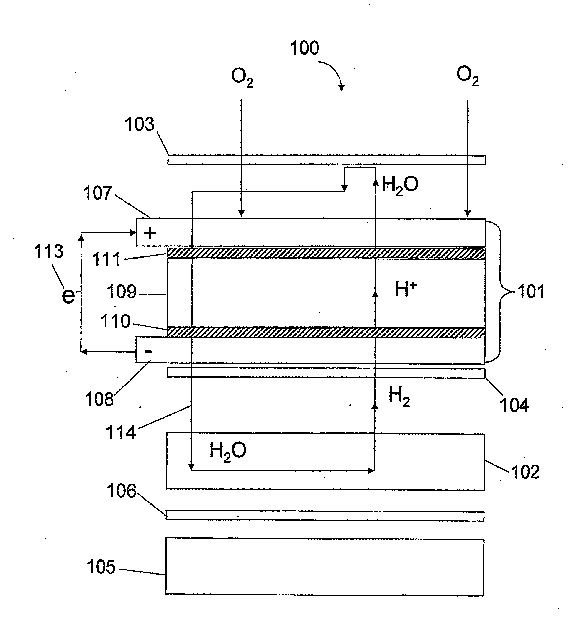
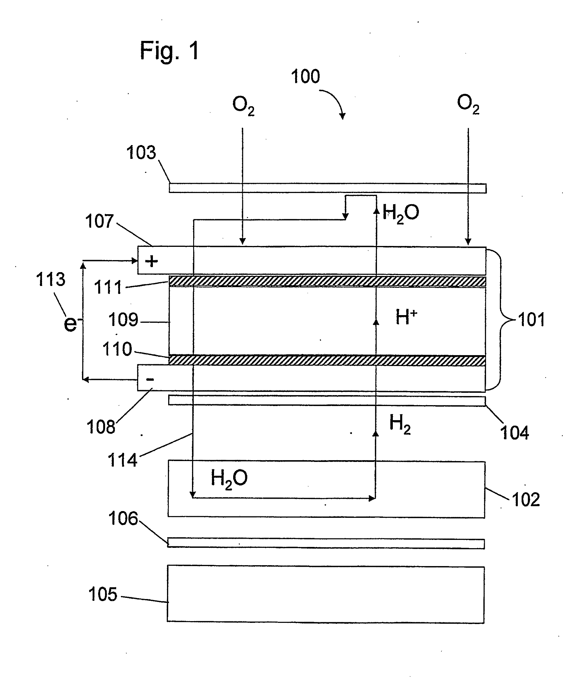
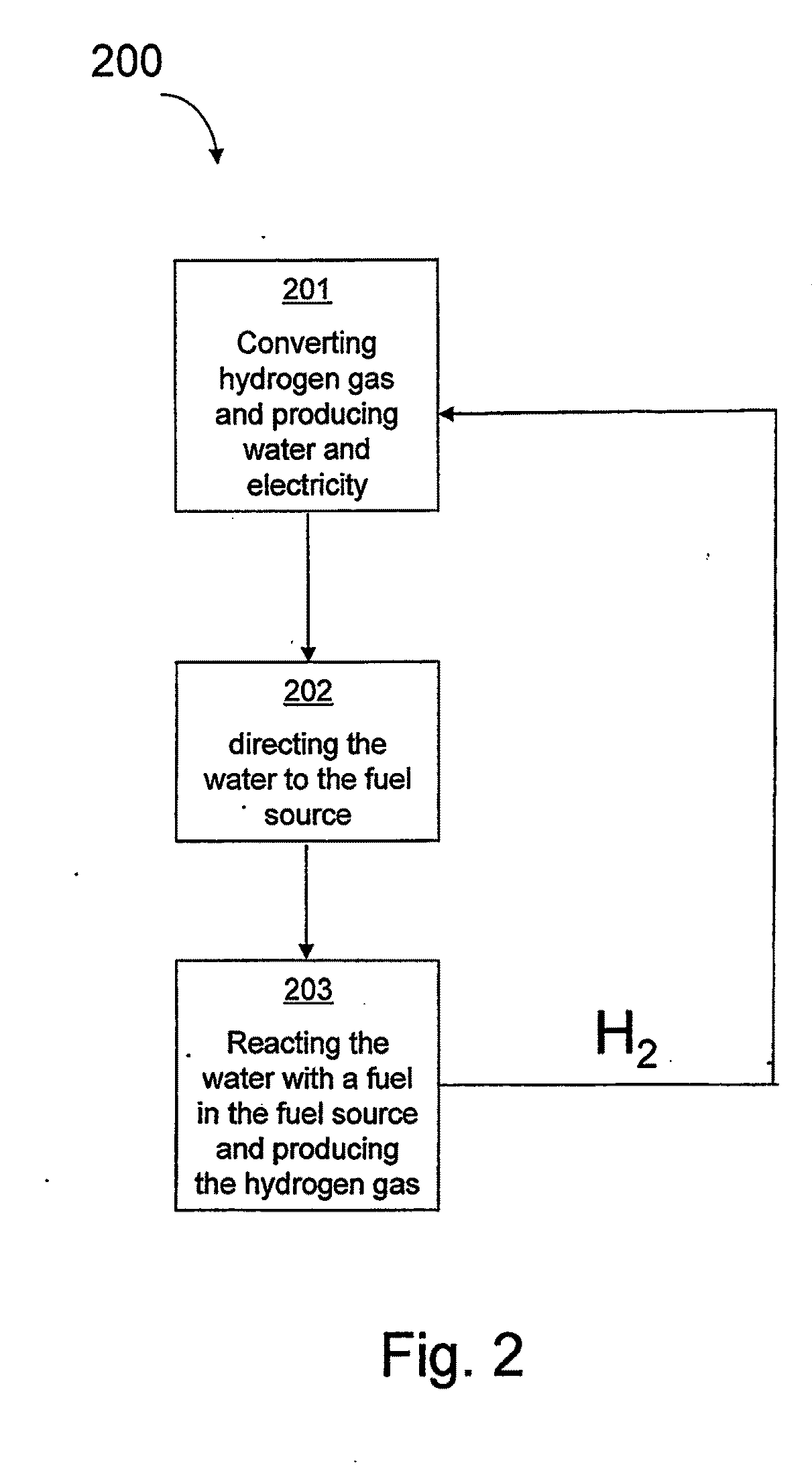
Described here is a device for generating electrical current via an electrochemical fuel cell that consumes hydrogen. The described device may be entirely or partially self-contained or may be made up of cooperating components. The device comprises at least and fuel and fuel cell components and those components may be integrated. The fuel is selected to produce hydrogen suitable for use in a variety of fuel cell designs that utilize hydrogen to produce electrical current. The fuel cell, in some variations, produces water and that water may be returned to the selected fuel source to create a self-sustaining supply of hydrogen for the fuel cell under load. The fuel cell may also contain a system for controlling the amount of water produced by the fuel cell that gets delivered to the solid fuel.

Description

CROSS REFERENCE TO RELATED APPLICATIONS[0001]This application claims the benefit of U.S. Provisional Patent Application No. 60 / 671,773, which is hereby incorporated by reference in its entirety as if fully put forth below.FIELD[0002]Described here is a device for generating electrical current via an electrochemical fuel cell that consumes hydrogen. The described device may be entirely or partially self-contained or may be made up of cooperating components. The device comprises a fuel source and fuel cell components and those components may be integrated. The fuel is selected to produce hydrogen for use in a variety of fuel cell designs that utilize hydrogen to produce electrical current. The fuel cell, in some variations, produces water and that water may be returned to the selected fuel source to create a self-sustaining supply of hydrogen for the fuel cell under load.BACKGROUND[0003]In the technological arena of devices that store and deliver electrical energy, many conventional c...

Claims


Application Information

Patent Timeline
Patent Type & Authority Applications(United States)
IPC IPC(8): H01M8/06H01M8/18
CPCH01M8/04156H01M8/04171H01M8/04208H01M8/04291H01M8/065H01M8/083H01M8/2475H01M2008/1095H01M2008/1293H01M2250/10H01M2250/30Y02E60/36Y02B90/10Y02E60/50
Inventor ZHOU, YU
Owner H2VOLT
Why Eureka
Try Eureka