
Electrochemical reactor bundles, stacks, and electrochemical reactor systems consisting of these components

a technology of electrochemical reactor and stack, applied in the direction of cell components, sustainable manufacturing/processing, final product manufacturing, etc., can solve the problems of large volume change, cell deformation and failure, and the occurrence of cell failure, etc., to achieve efficient collection and easy stacked

Inactive Publication Date: 2009-08-27
NAT INST OF ADVANCED IND SCI & TECH
View PDF6 Cites 30 Cited by
  • Summary
  • Abstract
  • Description
  • Claims
  • Application Information

AI Technical Summary

Benefits of technology

[0013]That is, an object of the present invention is to provide a novel collector method for bundle structures comprising the arrangement of micro-diameter tube cells as well as a stacking method using them. Another object of the present invention is to provide bundles which can be easily stacked and which allow current to be efficiently collected from tube electrochemical reactor cells having a cell structure capable of operating at a lower temperature, as well as the stacks composed thereof. Yet another object of the invention is to provide an electrochemical reactor system such as a solid oxide fuel cell utilizing the above tube electrochemical reactor cell stack.

Problems solved by technology

However, the anode support-type SOFCs with high power output that have been reported thus far are the flat type, which are susceptible to cell failure under extreme operating cycle conditions.
That is because the cells become deformed and fail as a result of the considerable change in volume in commonly used nickel cermet due to temperature changes and cycling in oxygen-reducing atmospheres.
An extremely important technical issue is therefore to find a way of enlarging and stacking flat SOFCs while preserving flat cell performance.
Controlling the electrode structure of the anode support substrate and making it thinner are important in terms of improving performance, but it has been difficult to further reduce the thickness and increase the porosity of flat types.
However, in conventional tubular cell bundles and stacks, the ends of the tubes are secured by collector parts (see FIG. 1), and the current design makes it difficult to join the tube ends with the collector parts, resulting in problems such as greater contact resistance, and less thermal shock resistance because the tubes are secured by collector parts.
This has led to greater difficult in controlling the position when electrode-collector plates are attached, and so far no new techniques allowing such problems to be overcome have yet been proposed in this technical field.

Method used


Image

  • Electrochemical reactor bundles, stacks, and electrochemical reactor systems consisting of these components
  • Electrochemical reactor bundles, stacks, and electrochemical reactor systems consisting of these components
  • Electrochemical reactor bundles, stacks, and electrochemical reactor systems consisting of these components

Examples


example 1

[0085]In this example, a tube electrochemical reactor cell was produced according to the following procedures. FIG. 7 illustrates the appearance of the tubular structure that was made. First, nitrocellulose was added as a binder to NiO (Wako) and a powder having a CeO2-10 mol % Gd2O3 (GDC) composition (Anan Kasei), and the ingredients were kneaded with water into a clayish paste which was then extruded into a tubular molding. The resulting tubular molding had a diameter of 1 mm and a tube thickness of 0.2 mm.

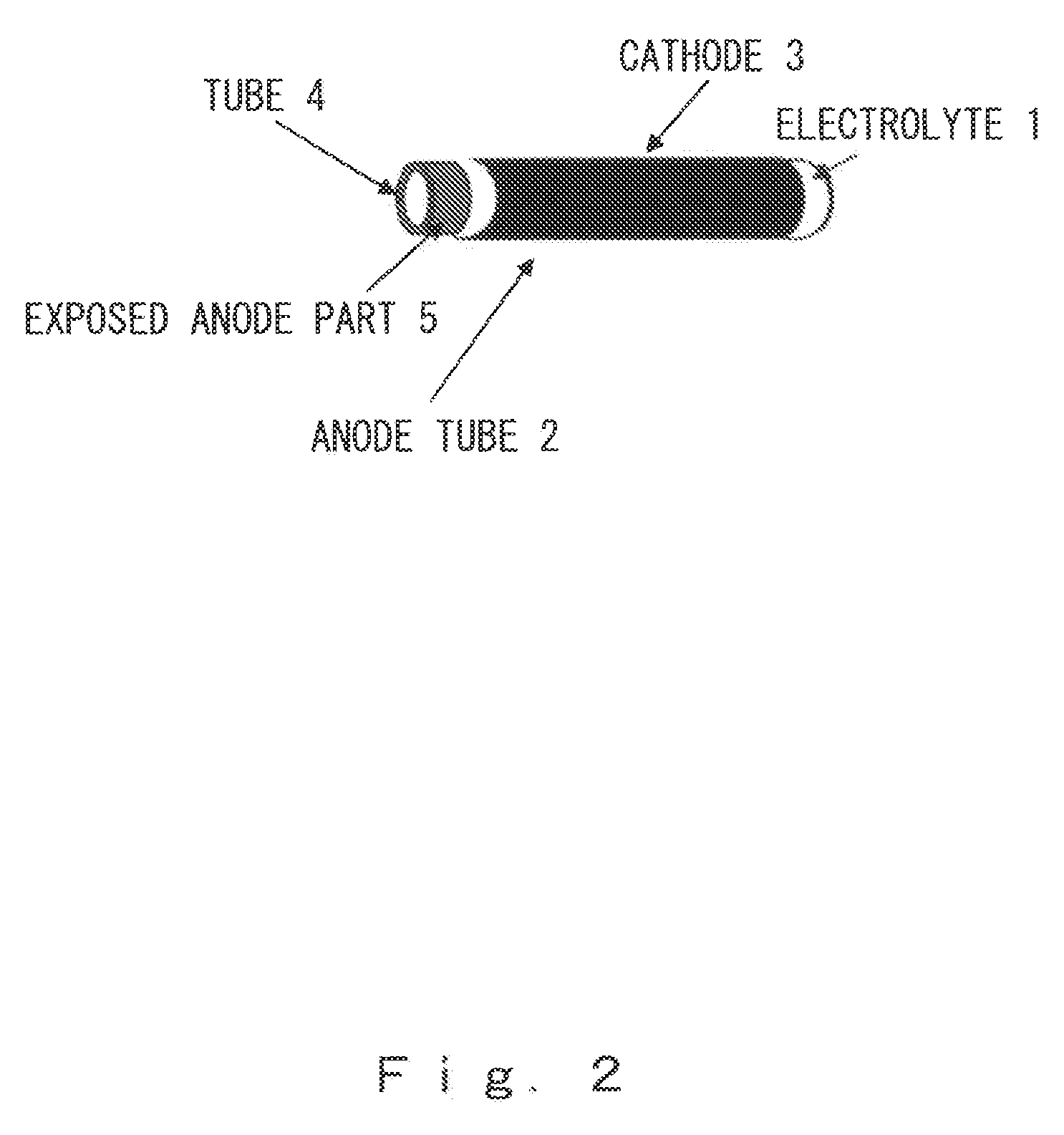
[0086]The opening at one end of the resulting tubular molding was then sealed with vinyl acetate, and the tube was dipped in a slurry containing a solid electrolyte with a GDC composition, thus dip coating an electrolyte layer-forming layer and giving an electrolyte-coated molded tube. 3 mm at the other end of the porous anode tube was left bare, forming the exposed anode part.

[0087]The tubular molding was then dried and then baked for 2 hours at 1400° C., giving an electrolyte-...

example 2

[0090]The tube electrochemical reactor stack obtained in Example 1 was connected to a gas introduction pipe (see FIG. 5). The connections were sealed with ceramic paste, and hydrogen and air were supplied as fuel gas through the fuel manifold 17 and air manifold 18 to the tube electrochemical reactor stack 12. Then, as shown in FIG. 10, the stack temperature and gas outlet temperature were measured with a stack temperature-measuring thermocouple 19 and a waste gas temperature-measuring thermocouple 20. FIG. 11 shows the results at stack temperatures of 400 to 490° C. as the power generating properties of the 4-bundle stack (volume 0.8 cc). It could be demonstrated that a stack no greater than 1 cc was capable of generating power equal to a stack voltage of 3.6 V and a voltage of 2 W or more at a low temperature of no more than 500° C.

example 3

[0091]The tube electrochemical reactor stack obtained in Example 1 was subjected to a rapid start / stop test. The cell performance was measured over time during repeated cycles of 150° C.→400° C. (start time: 3 min) and 400° C.→150° C. (stop time: 10 min) as shown in FIG. 12 (left). The results are given in FIG. 12 (right), indicating a constant output that was virtually unaffected by rapid starts and stops.

[0092]Embodiments of the present invention were explained in detail above, but the present invention is not limited to these embodiments and is capable of various modifications within the scope of the invention. For example, the embodiments above were examples of only single stacks, but structures comprising further building up of stacks can be produced by the same procedures.

[0093]As described above, the present invention relates to tube electrochemical reactor cell bundles and stacks, as well as an electrochemical reactor system composed thereof, whereby the present invention ca...


PUM

PropertyMeasurementUnit
Temperatureaaaaaaaaaa
Diameteraaaaaaaaaa
Diameteraaaaaaaaaa

Abstract

Tube electrochemical reactor bundle or stack, having a structure, in which a plurality of tube fuel cells, formed of a dense ion conductor (electrolyte) and cathode (air electrode) laminated to an anode (fuel electrode) material having a tube structure, are electrically connected by a thin metallic wire, and an electrochemical reactor system using them are provided.

Description

BACKGROUND OF THE INVENTION[0001]1. Field of the Invention[0002]The present invention relates to an electrochemical reactor cell stack and to an electrochemical reactor system such as a solid oxide fuel cell formed of such a reactor cell stack, and more specifically relates to an electrochemical reactor system employing tube electrochemical reactor cells which are capable of dramatically increasing the output per unit volume through the use of specific electrochemical reactor bundles and stacks. The present invention provides novel techniques and novel products related to electrochemical reactor cell bundles and stacks as well as electrochemical reactor systems employing such reactor cell stacks, which are suitable for use as clean energy sources and environmental purification devices.[0003]2. Description of the Related Art[0004]Solid oxide fuel cells (SOFC) are known as typical electrochemical reactors. An SOFC is a fuel cell in which an ion-conductive solid oxide electrolyte is us...

Claims


Application Information

Patent Timeline
IPC IPC(8): H01M8/10C25C7/00H01M50/77
CPCH01M8/004H01M8/1213Y02E60/50H01M8/243H01M8/1246Y02P70/50H01M8/2485H01M8/2404
Inventor SUZUKI, TOSHIOYAMAGUCHI, TOSHIAKIFUJISHIRO, YOSHINOBUAWANO, MASANOBU
Owner NAT INST OF ADVANCED IND SCI & TECH
Learn More