Glass-Ceramic with laminates

a technology of glass-ceramic and laminates, applied in the field of ballistic armor, can solve the problems of not being able to adapt to the need for transparency severely limits the material choice for the fabrication of the hard face of the transparent protective system, and the advances are not readily applicable in the field of transparent protective structures, etc., to achieve the effect of sufficient thickness and strength, sufficient thickness and strength

Active Publication Date: 2009-09-03
ORAN SAFETY GLASS INC
View PDF34 Cites 44 Cited by
  • Summary
  • Abstract
  • Description
  • Claims
  • Application Information

AI Technical Summary

Benefits of technology

[0017]The hard face is defined by a layer fabricated from a glass-ceramic substance having a hardness and compressive strength, both in dynamic conditions and standard temperature and pressure conditions, sufficient to substantially absorb at least a portion of the impact from an incoming projectile. The resilient layer is a layer selected to have a sufficient thickness and strength to withstand stresses imparted to the resilient layer under ballistic impact of the hard face. Furthermore, the resilient layer is selected to have a refractive index sufficiently similar to the refractive index of the hard face such that the transparent armor system is substantially transparent. In certain embodiments, the resilient layer is fabricated from a polymer material.
[0018]In one embodiment, at least one reinforcing layer is disposed behind the hard face opposite the incoming projectile. The reinforcing layers are each fabricated from a glass-ceramic substance having a hardness and compressive strength sufficient to substantially absorb at least a portion of the impact from an incoming projectile. In one embodiment, one resilient layer defines a covering and is laminated to a front surface of the hard face. Another resilient layer defines a backing and is laminated to a rear surface of the hard face. The covering

Problems solved by technology

These advances, unfortunately, have not been readily applicable to those areas where a transparent protective structure is required.
Neither the high-strength, hard ceramics nor the laminated fibrous backing materials are typically transparent, and so neither are adaptable to transparent protective structures.
The need for transparency severely limits possible choices of materials for fabrication of the hard face of transparent protective systems.
Although recent advances have been demonstrated in use of hot-pressed spinel or aluminum oxynitride (ALON) ceramics, or melt grown aluminum oxide (sapphire) crystal sheets for the hard face, manufacturing cost and size limitations would seem to restrict their use in all but the most critical of situations.
Such increase i

Method used


Image

  • Glass-Ceramic with laminates
  • Glass-Ceramic with laminates
  • Glass-Ceramic with laminates

Examples


Embodiment Construction

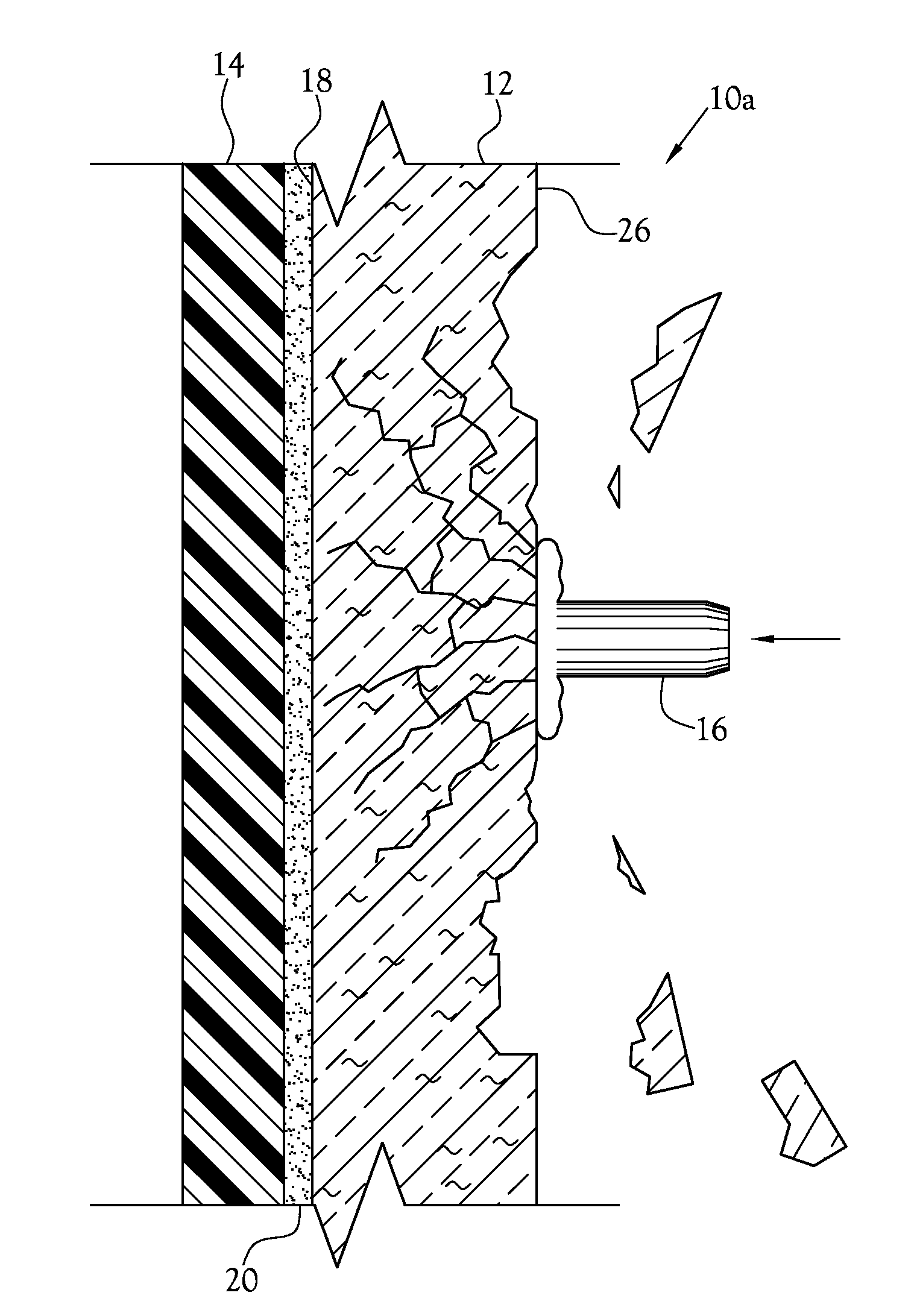
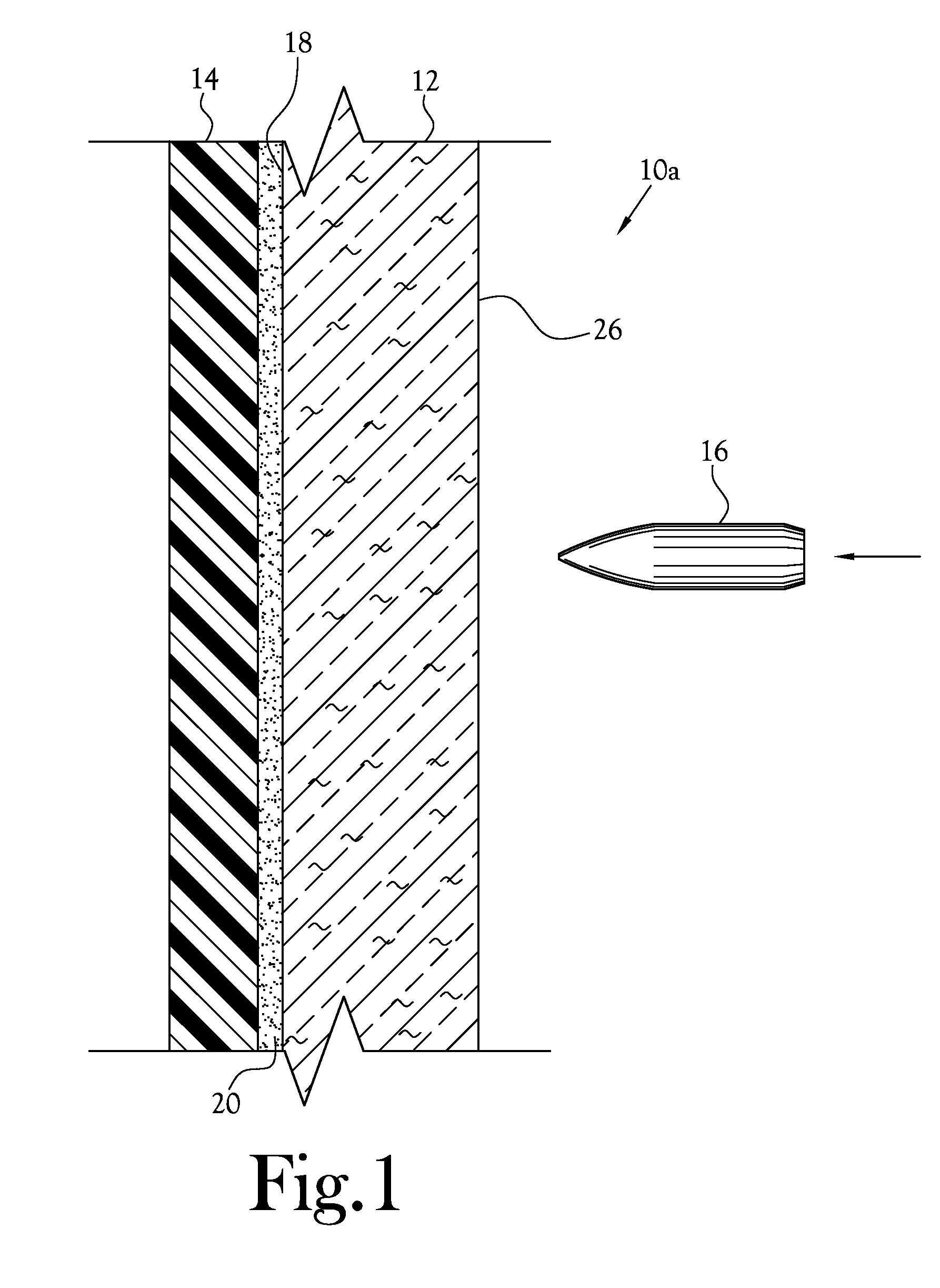
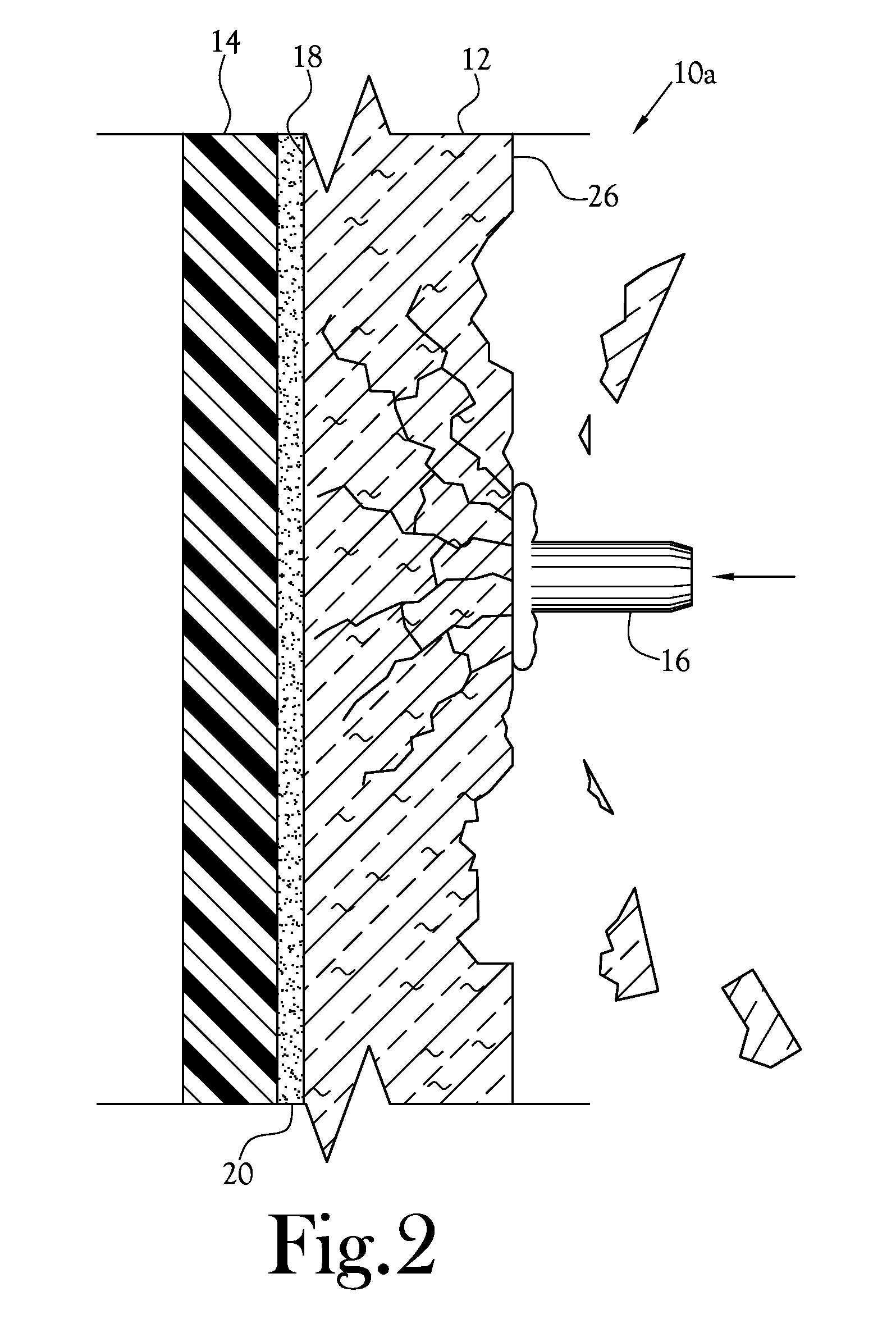
[0035]A transparent armor system for limiting the transfer of impact force from a projectile and corresponding method of manufacture is disclosed herein. The transparent armor system is illustrated generally at 10 in the figures. With reference to FIG. 1, one embodiment of the transparent armor system 10a includes a hard face 12 and a resilient layer 14 covering a rear surface 18 of the hard face 12 opposite an anticipated incoming projectile 16.

[0036]The hard face 12 is defined by a layer fabricated from a glass-ceramic substance having a hardness and compressive strength sufficient to substantially absorb at least a portion of the impact from an incoming projectile 16. The hard face 12 defines a front surface 26 configured to face an incoming projectile 16 and a rear surface 18 configured opposite an incoming projectile 16. It is understood that the specific type of glass-ceramic material suitable for use in the hard face 12 depends upon the mass, velocity, and impact characterist...


PUM

PropertyMeasurementUnit
Fractionaaaaaaaaaa
Fractionaaaaaaaaaa
Nanoscale particle sizeaaaaaaaaaa

Abstract

A transparent armor system includes a hard face fabricated from a substantially transparent glass-ceramic material exhibiting crystalline bodies throughout the mass of the glass-ceramic material and a backing covering a rear surface of the hard face opposite an anticipated incoming projectile. The backing has a refractive index substantially matching that of the hard face such as to allow substantial transparency of the transparent armor system. The hard face serves to disburse energy caused by the impact of an incoming projectile with the transparent armor system, while the backing serves to retain any pieces of the hard face fractured during ballistic impact. In certain embodiments, a plurality of hard faces are held in parallel and spaced apart arrangement.

Description

CROSS-REFERENCE TO RELATED APPLICATIONS[0001]This application is a Continuation-In-Part of U.S. application Ser. No. 11 / 689,299, filed Mar. 21, 2007.STATEMENT REGARDING FEDERALLY-SPONSORED RESEARCH OR DEVELOPMENT[0002]Not ApplicableBACKGROUND OF THE INVENTION[0003]1. Field of Invention[0004]This invention relates to ballistic armor. More specifically, this invention relates to a transparent armor system utilizing a multi-layer structure incorporating glass-ceramics and laminates.[0005]2. Description of the Related Art[0006]In order to provide protection of personnel and equipment from ballistic projectiles, explosive ordnance, and forces and objects from detonation of improvised explosive devices (collectively hereinafter “projectiles”), it is necessary to provide a means of disbursing the kinetic energy of such projectiles to prevent them from reaching their target. Although this may be accomplished by interposing a large mass of any of a number of different materials between the t...

Claims


Application Information

Patent Timeline
IPC IPC(8): F41H5/04
CPCB32B17/10036B32B17/10045B32B17/10119F41H5/0428B32B17/1077F41H5/0407B32B17/10761
Inventor CARBERRY, JOHNBOYETT, JOHNCLINE, CARLMIRATA, MARCELLALEIGHTON, KATHERINE T.SERAFIN, WIKTORALESHIRE, EDGAR
Owner ORAN SAFETY GLASS INC
Why Eureka
Try Eureka