Electrooptic device

a technology of optical deflectors and optical deflectors, applied in the field of optical deflectors, can solve the problems of limited rotational speed, inadequacies of polygon mirrors, and inability to meet the requirements of rapid operation, and achieve the effects of reducing the angle of shifting between vertically polarized light and horizontally polarized light, reducing beam deflection, and increasing beam deflection

Active Publication Date: 2009-09-03
NIPPON TELEGRAPH & TELEPHONE CORP
View PDF5 Cites 23 Cited by
  • Summary
  • Abstract
  • Description
  • Claims
  • Application Information

AI Technical Summary

Benefits of technology

[0028]According to an electrooptic device for the present invention, a space charge is generated inside an electrooptic crystal by applying a voltage to the electrooptic crystal, and a tilt of the electric field is produced in cross section relative to the light axis of a beam that enters. When the tilt of the

Problems solved by technology

Since a method employing a polygon mirror utilizes mechanical rotations, the rotational speed is limited.
That is, the acquisition of revolutions equal to or greater than 10000 rpm is difficult for a polygon mirror, and there is a fault in that a polygon mirror is not appropriate for an application required for a rapid operation.
However, the limit imposed by the rotational speed of a polygon mirror is a bottleneck when it comes to increasing the printing speed of a printer.
However, since the drive coil of a conventional galvano mirror is provided by a machine winding, downsizing is difficult.
Therefore, it is difficult for the sizes of a laser scanning system employing a galvano mirror and a laser application apparatus that employs this system to be further reduced.
Furthermore, there is a fault that power consumption is large.
There is another fault in that a rapid operation can not be performed within a cycle of the MHz unit.
However, a method employing this optical deflector of an optical diffraction type consumes a large amount of power and downsizing is difficult.
Further, there is a fault in that it is difficult to obtain a large deflection angle and

Method used


Image

  • Electrooptic device
  • Electrooptic device
  • Electrooptic device

Examples


embodiment 1

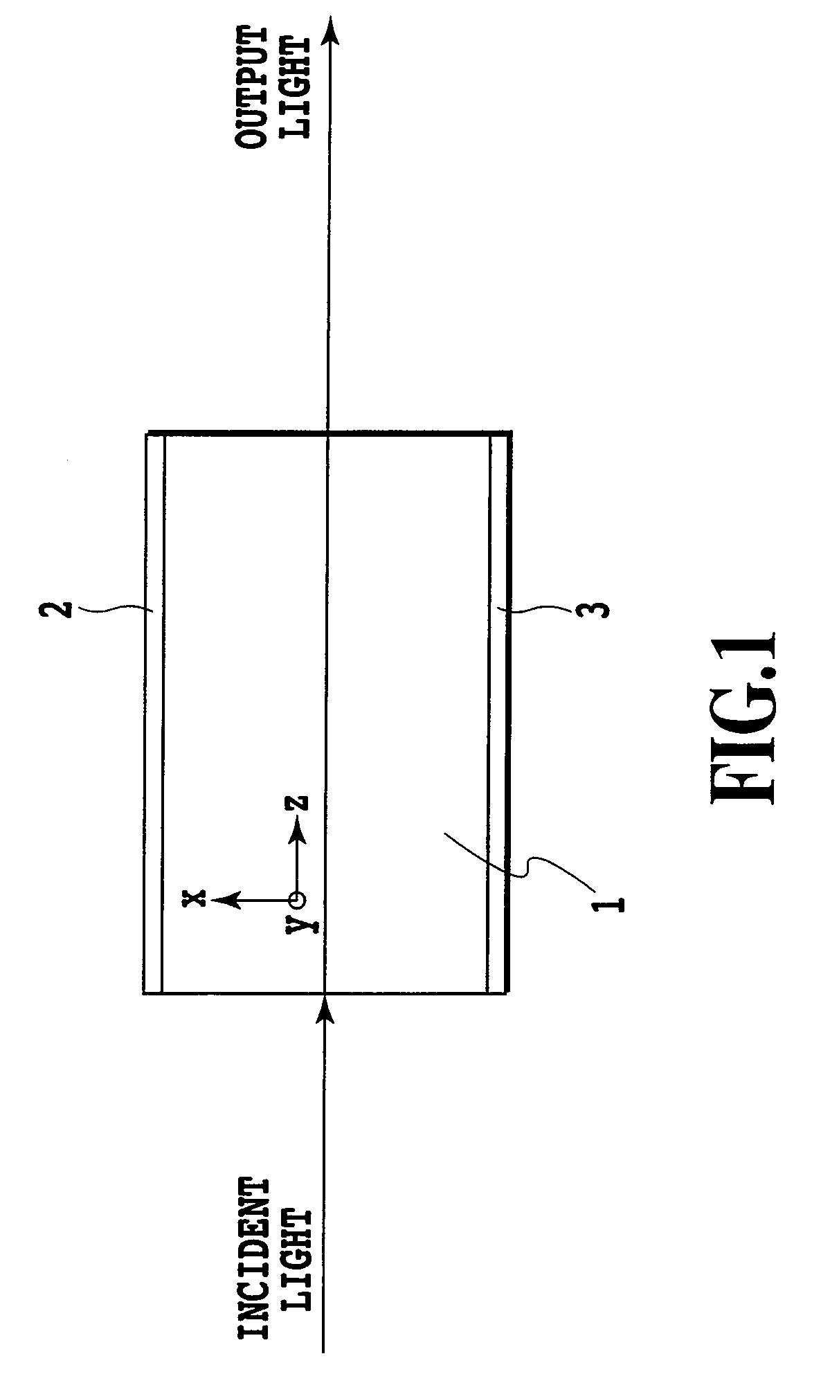
[0110]FIG. 15 shows an electrooptic device of a parallel-plate electrode type according to embodiment 1 of the present invention. A KLTN crystal (in K1-yLiyTa1-xNbxO3, x=about 0.40 and y=about 0.001) is cut in the shape of a rectangle, and an electrooptic crystal 11, of which four faces are polished, is prepared. A positive electrode 12 and a negative electrode 13 made of Ti / Pt / Au are formed on the upper face and the lower face of the electrooptic crystal 11. The size of the electrooptic crystal 11 is 6 mm (z axis)×5 mm wide (y axis)×0.5 mm thick (x axis), and the size of each electrode is 5 mm long×4 mm wide. In this specification, Ti / Pt / Au is used to indicate that Pt and Au are laminated, in this order, on a lowermost layer of Ti.

[0111]The KLTN crystal is an electrooptic crystal having an electrooptic constant that is great near the phase transition from the cubic system to the tetragonal system. Since the phase transition temperature of the KLTN crystal employed for the embodimen...

embodiment 2

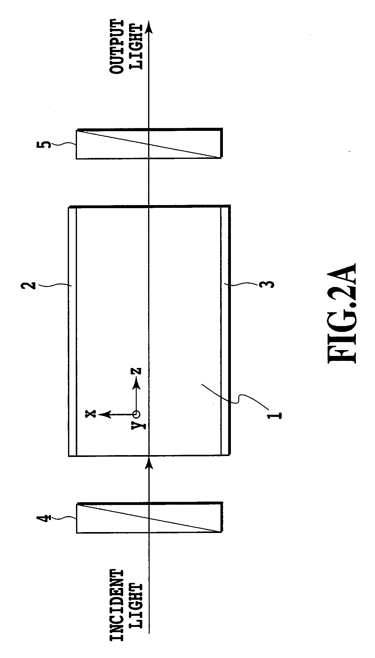
[0119]FIG. 18 shows qn electrooptic device of a horizontal electrode type according to embodiment 2 of the present invention. A KLTN crystal (in K1-yLiyTa1-xNbxO3, x=about 0.40 and y=about 0.001) is cut into the shape of a rectangle, and an electrooptic crystal 21 of which four faces are polished is prepared. A positive electrode 22 and a negative electrode 23 made of Ti / Pt / Au are formed on the upper face of the electrooptic crystal 21. The size of the electrooptic crystal 21 is 6 mm (z axis)×5 mm wide (y axis)×0.5 mm thick (x axis), and the size of each electrode is 5 mm long.

[0120]The KLTN crystal is an electrooptic crystal that has an electrooptic constant that is great near the phase transition from the cubic system to the tetragonal system. Since the phase transition temperature of the KLTN crystal employed for the embodiment 2 is 55° C., a Peltier device and a resistance bulb are employed to set the temperature of this device to 60° C., which is higher by about 5° C. than the ...

embodiment 3

[0126]FIG. 20 shows a light beam deflector according to embodiment 3 of the present invention. For the light beam deflector, a positive electrode 32 and a negative electrode 33 are formed on opposite faces of a block electrooptic crystal 31. The electrooptic crystal 31, which is a KLTN crystal, is cut to a size 6 mm long (z axis)×5 mm wide (y axis)×0.5 mm thick (x axis), and electrodes 5 mm long×4 mm wide are attached to the opposite faces. The relative permittivity of the KLTN crystal for this embodiment is 6300 at the measurement temperature of 20° C. Ti / Pt / Au is employed as the electrode material. FIG. 21 shows a distribution of the refractive index change in the light beam deflector for the embodiment 3 of the present invention. A distribution is shown for the fluctuation, when a voltage applied between the positive and negative electrodes is changed, of a refractive index of light that vertically advances. The vertical axis represents the change in a refractive index when no vo...


PUM


Abstract

An electrooptic device having a simple structure that can efficiently increase deflection of a beam is provided. The device includes: an electrooptic crystal (11) having an electrooptic effect; an electrode pair of a positive electrode (12) and a negative electrode (13) for generating an electric field inside the electrooptic crystal; and a power source for applying a voltage between the electrode pair so as to generate a space charge inside the electrooptic crystal. With this arrangement, by using a simple structure, a change in a deflection angle is temporally rapid, and a large deflection angle that can not be obtained by a conventional electrooptic crystal prism can be acquired at a low applied voltage.

Description

TECHNICAL FIELD[0001]The present invention relates to an electrooptic device, and more particularly relates to an electrooptic device that changes the refractive index of an electrooptic crystal by controlling the electric field of the crystal, so that the forwarding direction of light can be changed, or the phase of light can be changed.BACKGROUND ART[0002]At present, requests for an optical control device that deflects a laser beam have increased for video apparatuses, such as projectors, laser printers, confocal microscopes having a high resolution, barcode readers, etc. As optical deflection techniques, a technique for rotating a polygon mirror, a technique for employing a galvano mirror to control the deflected direction of light, a diffraction technique that employs the acousto-optic effect, and a micro machine technique called the MEMS (Micro Electro Mechanical System) have been proposed.[0003]As for a polygon mirror, a mirror having the shape of a polyhedron is mechanically ...

Claims


Application Information

Patent Timeline
IPC IPC(8): B41J2/47G02F1/03
CPCG02F1/03G02F1/0316G02F2001/291G02F1/29G02F1/0322G02F1/291
Inventor NAKAMURA, KOUICHIROUFUJIURA, KAZUOIMAI, TADAYUKIMIYAZU, JUN
Owner NIPPON TELEGRAPH & TELEPHONE CORP
Why Eureka
Try Eureka