Optical Pule Amplifier with High Peak and High Average Power

a technology of optical pulse amplifier and peak power, which is applied in the field of optical pulse amplifier, can solve the problems of difficult to cool the bulk within the cavity, low repetition rate of such optical pulse amplifier, and inability to obtain high peak power, and achieves the effect of high peak power, easy cooling, and high surface/volume ratio of optical fibers

Inactive Publication Date: 2009-09-03
TELENOR AS
View PDF12 Cites 22 Cited by
  • Summary
  • Abstract
  • Description
  • Claims
  • Application Information

AI Technical Summary

Benefits of technology

[0011]With an optical pulse amplifier according to the invention, the output pulse signal that are generated by the plurality of optical fiber amplifiers are all coherent because they are based on the splitting of one input pulse. Thus, the power of the individual output pulse signals are added to obtain the power of the global signal generated by the amplifier. Such an amplifier can thus generate high peak power, when the number of optical fiber amplifiers is sufficient and/or if the duration of the input pulse is short enough.
[0012]Moreover, as the surfa

Problems solved by technology

However, such an optical pulse amplifier suffers the disadvantage that it is hard to cool the bulk within the cavity, mainly because the surface/volume ratio is too high.
Consequently, the repetition rate of such an optical pulse amplifier is very low.
Thus, in the prior art, it was impossible to obtain high peak pow

Method used


Image

  • Optical Pule Amplifier with High Peak and High Average Power
  • Optical Pule Amplifier with High Peak and High Average Power
  • Optical Pule Amplifier with High Peak and High Average Power

Examples


Embodiment Construction

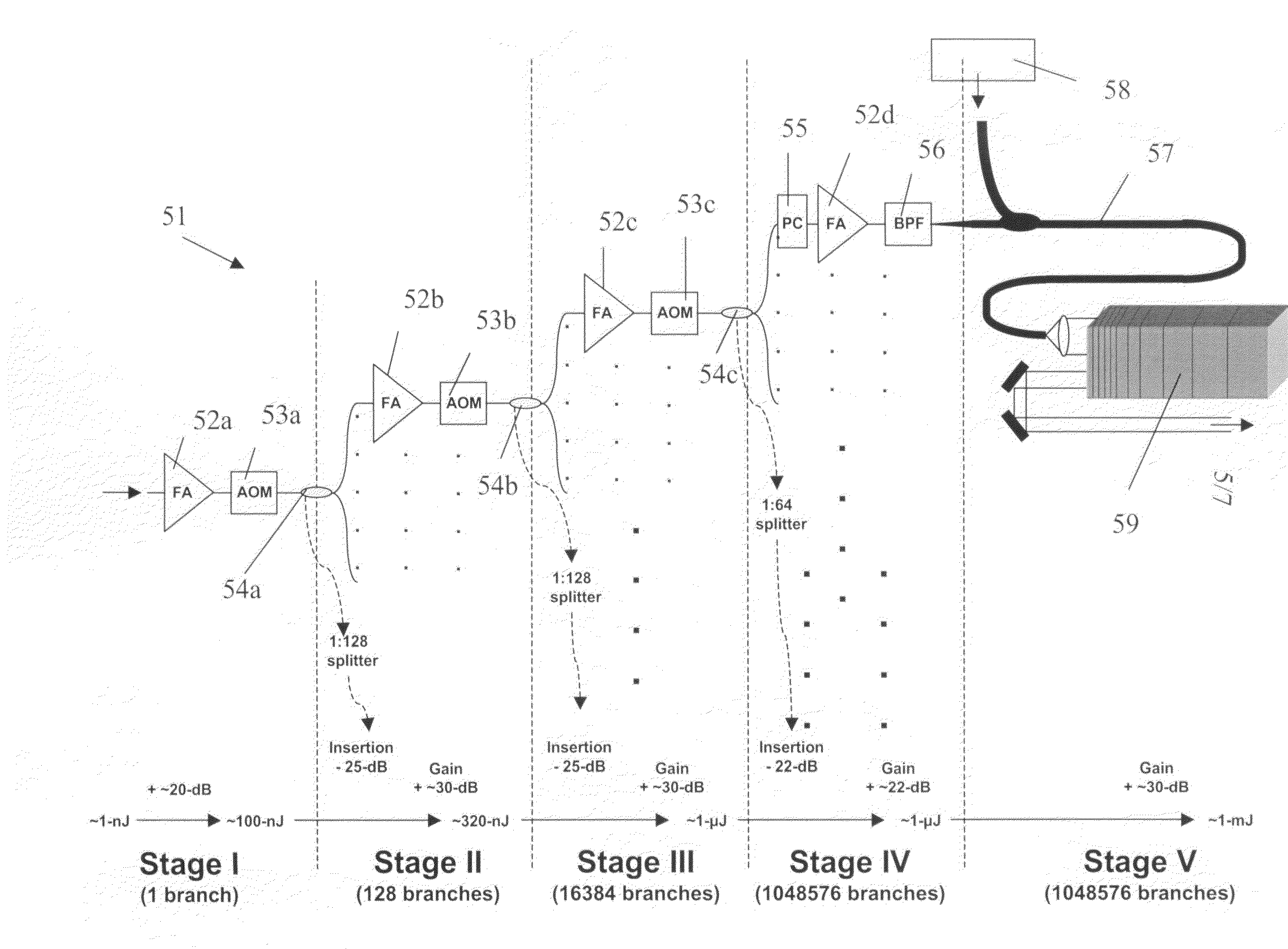
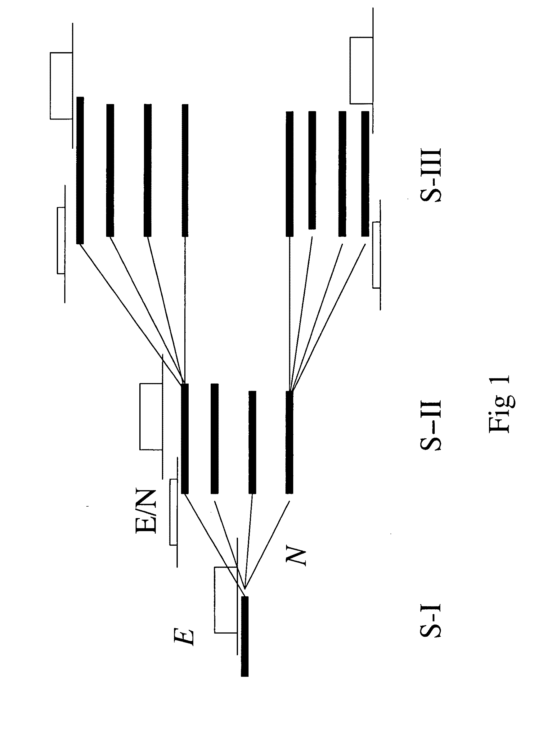
[0027]As schematically illustrated FIG. 1, an amplifier according to the invention comprises identical fiber-CPA sections 12. The last stage of the amplifier comprises Nt identical fibers. The network is composed of n stages SI, SII, SIII. Each stage consists of N fibers. For cost reasons, all these fibers are identical and identically pumped.

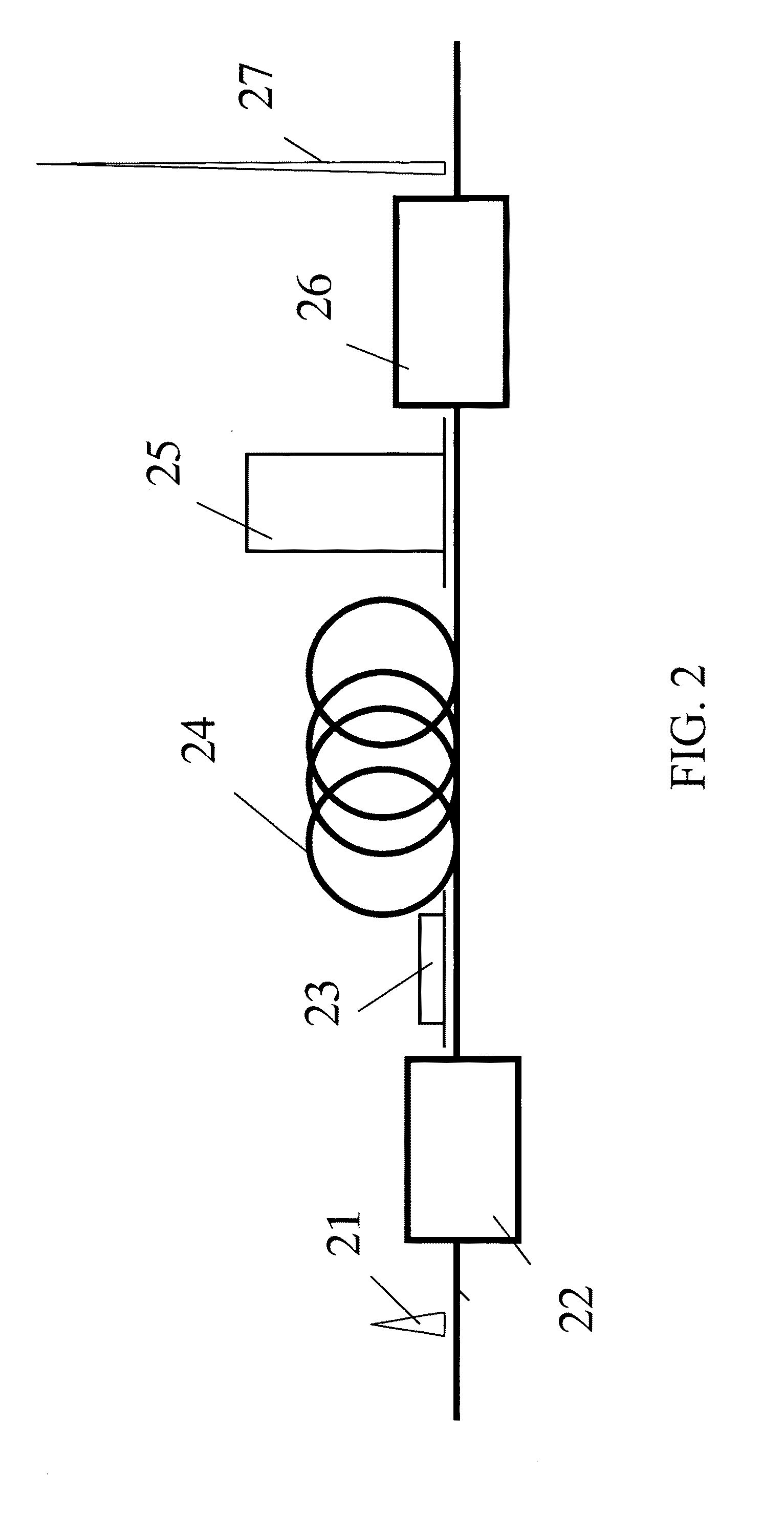
[0028]The Chirped Pulse Amplification in such fibers has been described and demonstrated in Advanced Solid State Lasers, 2001, Seattle, Wash., January, Galvanauskas, et al. “Millijoule femtosecond fiber-CPA system”. Illustrated FIG. 2, a pulse 21 is stretched by a stretcher 22 to produce a stretched pulse 23. The stretched pulse 23 is then amplified by a fiber amplifier 24 to produce an amplified stretched pulse 25. The amplified stretched pulse 25 is finally compressed by a compressor 26, to produce a amplified pulse 27.

[0029]In the system illustrated FIG. 1, the initial pulse is first stretched and amplified to a level E=Fs.A where Fs is the ...


PUM


Abstract

The invention relates to an optical pulse amplifier comprising
    • a first optical fiber amplifier adapted to receive an input pulse,
    • a splitter connected to said first optical fiber, said splitter having a plurality of outputs;
    • a plurality of optical fiber amplifiers, each optical fiber amplifier being connected to one of said plurality of outputs, said plurality of optical fiber amplifiers generating a plurality of output pulse signals.
The optical pulse amplifier of the invention has the advantage that it can produce high peak and high average power.

Description

CROSS REFERENCE TO RELATED APPLICATIONS[0001]This is a National Phase entry of PCT / FR2006 / 002657, filed Sep. 21, 2006, which claims priority to European Application No. EP 05291957.8, filed Sep. 21, 2005; both of which are incorporated by reference herein.BACKGROUND AND SUMMARY[0002]This invention relates to an optical pulse amplifier.[0003]Optical pulse amplifiers are known in the art. Usually, optical pulse amplifiers comprise a laser cavity. Within the laser cavity, a bulk is pumped by a laser diode generating a pulse signal. The pulse signal is amplified by the bulk and an output high energy pulse signal is generated. Such technology is for example used for obtaining high energy laser, such as a megajoule Laser. However, such an optical pulse amplifier suffers the disadvantage that it is hard to cool the bulk within the cavity, mainly because the surface / volume ratio is too high. Consequently, the repetition rate of such an optical pulse amplifier is very low.[0004]In the past t...

Claims


Application Information

Patent Timeline
IPC IPC(8): H01S3/23H01S3/067
CPCH01S3/0057H01S3/2383H01S3/06758Y02E30/10
Inventor MOUROU, GERARDGALVANAUSKAS, ALMANTASHULIN, DANIEL
Owner TELENOR AS
Why Eureka
Try Eureka