Electrode for plasma processing apparatus, plasma processing apparatus, plasma processing method and storage medium

a plasma processing apparatus and plasma technology, applied in the direction of electrical equipment, basic electric elements, electric discharge tubes, etc., can solve the problems of reducing the intensity of the electric field around the periphery of the wafer, substantially difficult to optionally control the distribution of the electric field, and cannot solve the above problems in nature. uniformity of the electric field of the plasma, enhanced uniformity of the electric field of the plasma

Inactive Publication Date: 2009-09-03
TOKYO ELECTRON LTD
View PDF7 Cites 179 Cited by
  • Summary
  • Abstract
  • Description
  • Claims
  • Application Information

AI Technical Summary

Benefits of technology

[0037]Alternatively, the present invention is a storage medium for storing therein a computer program for driving a computer to execute a plasma processing method, wherein the plasma processing method uses a plasma processing apparatus including an upper electrode, a table constituting a lower electrode, a processing vessel configured for containing the upper electrode and the lower electrode therein, and a first high frequency power source connected with the lower electrode and used for generating plasma, wherein the upper electrode and the lower electrode are arranged to be opposed to each other, and wherein the plasma processing method comprises the steps of: supplying a dielectric into a dielectric injection space formed in the upper electrode; placing a substrate on the table; supplying a processing gas into the processing vessel; and changing the processing gas into the plasma between the upper electrode and the lower electrode, so as to perform a plasma process to the substrate with the plasma, wherein the step of supplying the dielectric is performed for controlling a supply amount of the dielectric, such that in-plane uniformity of intensity of an electric field of the plasma can be enhanced, as compared with the case in which the dielectric is not supplied into the dielectric injection space.
[0038]Alternatively, the present invention is a storage medium for storing therein a computer program for driving a computer to execute a plasma processing method, wherein the plasma processing method uses a plasma processing apparatus including an upper electrode, a table constituting a lower electrode, a processing vessel configured for storing the upper electrode and the lower electrode therein, a first high frequency power source connected with either one of the upper electrode and the lower electrode and used for generating plasma, and a second high frequency power source connected with the lower electrode and used for introducing ions present in the plasma, wherein the upper electrode and the lower electrode are arranged to be opposed to each other, and wherein the plasma processing method comprises the steps of: supplying a dielectric into a dielectric injection space formed in the upper electrode; placing a substrate on the table; supplying a processing gas into the processing vessel; and changing the processing gas into the plasma between the upper electrode and the lower electrode, so as to perform a plasma process to the substrate with the plasma, wherein the step of supplying the dielectric is performed for controlling a supply amount of the dielectric, such that in-plane uniformity of intensity of an electric field of the plasma can be enhanced, as compared with the case in which the dielectric is not supplied into the dielectric injection space.
[0039]Alternatively, the present invention is a storage medium for storing therein a computer program for driving a computer to execute a plasma processing method, wherein the plasma processing method uses a plasma processing apparatus including an upper electrode, a table constituting a lower electrode, a processing vessel configured for containing the upper electrode and lower electrode therein, and a first high frequency power source connected with the lower elec...

Problems solved by technology

However, such an extremely high frequency of the electric power applied to the apparatus may tend to considerably increase intensity of an electric field around a central portion of a surface of the electrode, i.e., a region corresponding to a central portion of the wafer, while relative...

Method used


Image

  • Electrode for plasma processing apparatus, plasma processing apparatus, plasma processing method and storage medium
  • Electrode for plasma processing apparatus, plasma processing apparatus, plasma processing method and storage medium
  • Electrode for plasma processing apparatus, plasma processing apparatus, plasma processing method and storage medium

Examples


example 1

[0101]Under the following conditions, the simulation as described above was performed. In this simulation, the magnitude of the sheath electric field was calculated, with the size of the recess 57 being fixed, while the relative permittivity of the dielectric in the recess 57 and the resistivity of the electrode plate 54 were changed, respectively.

(Simulation Conditions)

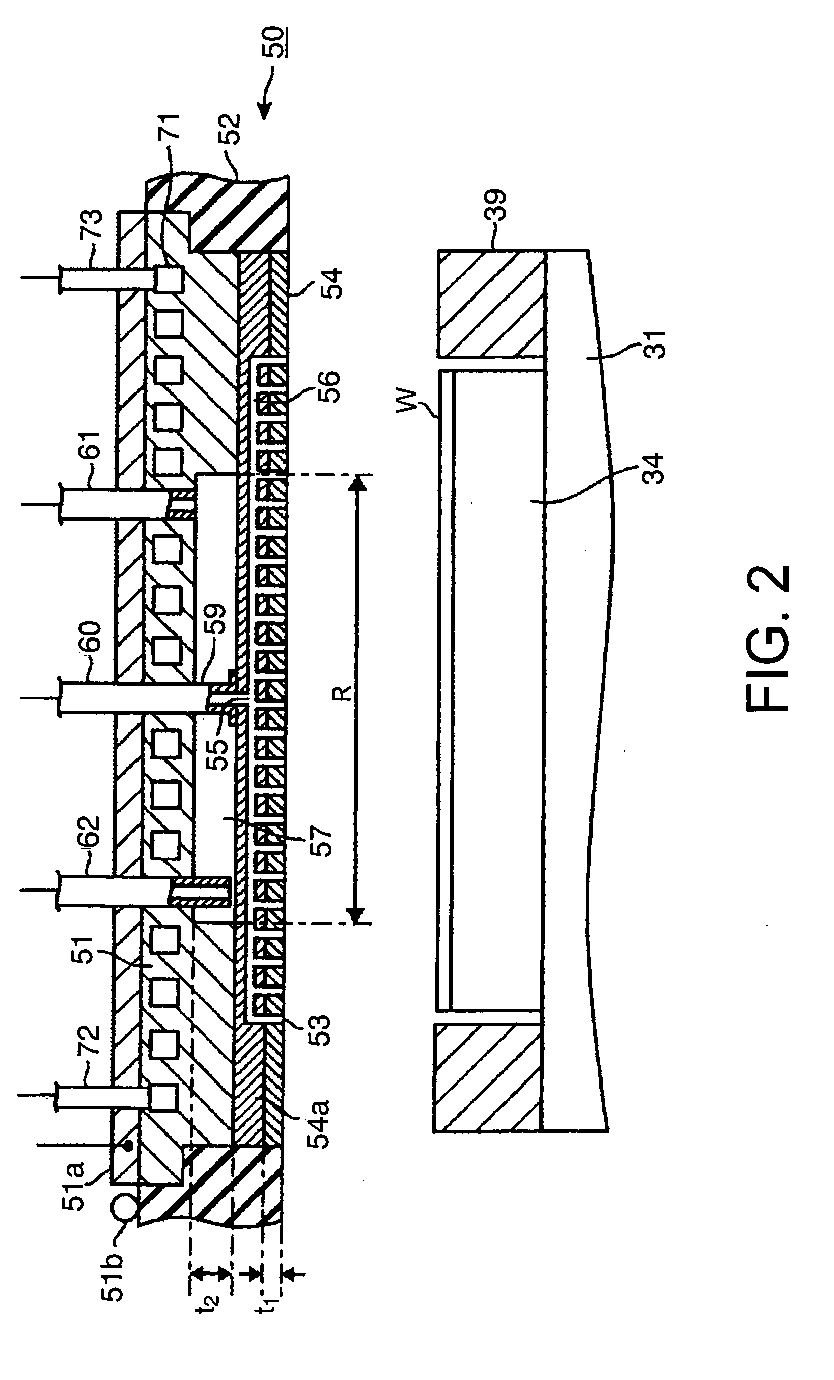
[0102]Diameter R of the recess 57: 100 mm

[0103]Thickness t2 of the recess 57: 5 mm

[0104]High frequency for the plasma generation: 100 MHz

[0105]Relative permittivity (∈) of the dielectric in the recess 57: 1 / 3.8 / 10 / 50

[0106]Resistivity (Ωm) of the electrode plate 54: no / 0.02 / 0.5 / 1 / 5 / 10

[0107]As the material actually used for setting the dielectric in the recess 57 at the relative permittivity as described above, a vacuum (∈: 1), powder of silicon dioxide (∈: 3.8), powder of ceramics, e.g., Al2O3 (∈: 10 to 50) and the like can be mentioned. In the case of setting the resistivity into the range as described above, each de...

example 2

[0111]Another simulation similar to the simulation in the above Example 1 was carried out, with the recess 57 having a 200 mm diameter R. As shown in FIGS. 12(a) to 12(e), it was found that the intensity of the electric field of the plasma can be reduced, over the region corresponding to the recess 57 (i.e., a region from the center of the wafer W to an approximately 100 mm radial point) can be reduced by gradually decreasing the relative permittivity of the recess 57, in the same manner as in the above simulation. Similarly, it was found that the intensity of the electric field of the plasma can be controlled, over the whole surface of the wafer W, by changing the resistivity of the electrode plate 54 together with the relative permittivity of the recess 57.

[0112]Additionally, as shown in FIG. 12(f), the intensity of the electric field of the plasma can be similarly controlled, by changing the relative permittivity of the dielectric in the recess 57 as well as by changing the thick...

example 3

[0113]Next, as shown in FIG. 13, still another simulation similar to the simulation in the above Example 1 was carried out, with the recess 57 having a 300 mm diameter R. Also in this simulation, it was found that the intensity of the electric field of the plasma can be reduced, over the region corresponding to the recess 57 (i.e., a region from the center of the wafer W to an approximately 150 mm radial point) can be reduced by gradually decreasing the relative permittivity of the recess 57, in the same manner as described above. Again, it was found that the intensity of the electric field of the plasma can be controlled, over the whole surface of the wafer W, by changing the resistivity of the electrode plate 54 together with the relative permittivity of the recess 57. From these results, it was found that the diameter R of the recess 57 is preferably set at a value less than the diameter of the support member 51, for example, 300 mm or less, because the sheath electric field (or ...


PUM

PropertyMeasurementUnit
Temperatureaaaaaaaaaa
Dielectric polarization enthalpyaaaaaaaaaa
Shapeaaaaaaaaaa

Abstract

The present invention provides an upper electrode used in an etching apparatus and the etching apparatus including the upper electrode, both of which can properly reduce intensity of electric field of plasma around a central portion of a substrate to be processed, thus enhancing in-plane uniformity of a plasma process. In this apparatus, a recess, serving as a space for allowing a dielectric to be injected therein, is provided around a central portion of the upper electrode. A dielectric supply passage configured for supplying the dielectric into the space and a dielectric discharge passage configured for discharging the dielectric from the space are connected with the space, respectively. With such configuration, the dielectric can be controllably supplied into the recess, such that in-plane distribution of the intensity of the electric field can be uniformed, corresponding to in-plane distribution of the intensity of the electric field of the plasma generated under various process conditions, such as a kind of each wafer that will be etched, each processing gas that will be used, and the like.

Description

CROSS REFERENCE TO RELATED APPLICATIONS[0001]This application is based on the prior Japanese Patent Application No. 2008-50745 filed on Feb. 29, 2008 and U.S. Provisional Patent Application No. 61 / 71556 filed on May 6, 2008, the entire contents of which are incorporated herein by reference.BACKGROUND OF THE INVENTION[0002]1. Field of the Invention[0003]The present invention relates to an upper electrode, a table (or lower electrode), a plasma processing apparatus including at least one of the upper electrode and table, a plasma processing method and a storage medium, each used for processing a substrate to be processed, such as a semiconductor wafer or the like, to which a plasma process is provided.[0004]2. Background Art[0005]In a step for manufacturing semiconductor devices, for example, a dry etching process, an ashing process and the like has been known, as the plasma process for processing the substrate by changing a processing gas into plasma. In an etching apparatus for perf...

Claims


Application Information

Patent Timeline
IPC IPC(8): H01L21/465C23F1/08
CPCH01J37/32091H01J37/3244H01J37/32009H01J37/32541H01J37/32449
Inventor HONDA, MASANOBUHIMORI, SHINJI
Owner TOKYO ELECTRON LTD
Why Eureka
Try Eureka