Dry etching method and apparatus

a dry etching and apparatus technology, applied in piezoelectric/electrostrictive device material selection, solid-state devices, device material selection, etc., can solve the problems of resolution decline, inability to achieve high precision processing, and low selectivity of etching objective body and resist used as etching masks. achieve satisfactory etching performance, speed up the etching rate, and high ion energy

Inactive Publication Date: 2009-09-10
FUJIFILM CORP
View PDF7 Cites 3 Cited by
  • Summary
  • Abstract
  • Description
  • Claims
  • Application Information

AI Technical Summary

Benefits of technology

[0018]According to the present invention, by applying a low-frequency bias voltage, even though an inert gas (e.g., argon gas) is not used as the processing gas, the ion energy is high and satisfa

Problems solved by technology

However, in the dry etching that uses the gas mixture of the inert gas and the fluorocarbon gas, there is a problem in that there is low selectivity with respect to the etching objective body and the resist that is used as the etching mask.
If the resist selectivity is low, then it is necessary to make the resist forming the mask thicker; however, if the resist is made thicker, then the resolution declines and high precision processing cannot be achieved.
Furthermore, if the etching rate is raised (speeded up), then it is not possible to ensure the selectivity with respect to the resist, and it is difficult to accelerate the etching rate.
On t

Method used


Image

  • Dry etching method and apparatus
  • Dry etching method and apparatus
  • Dry etching method and apparatus

Examples


Embodiment Construction

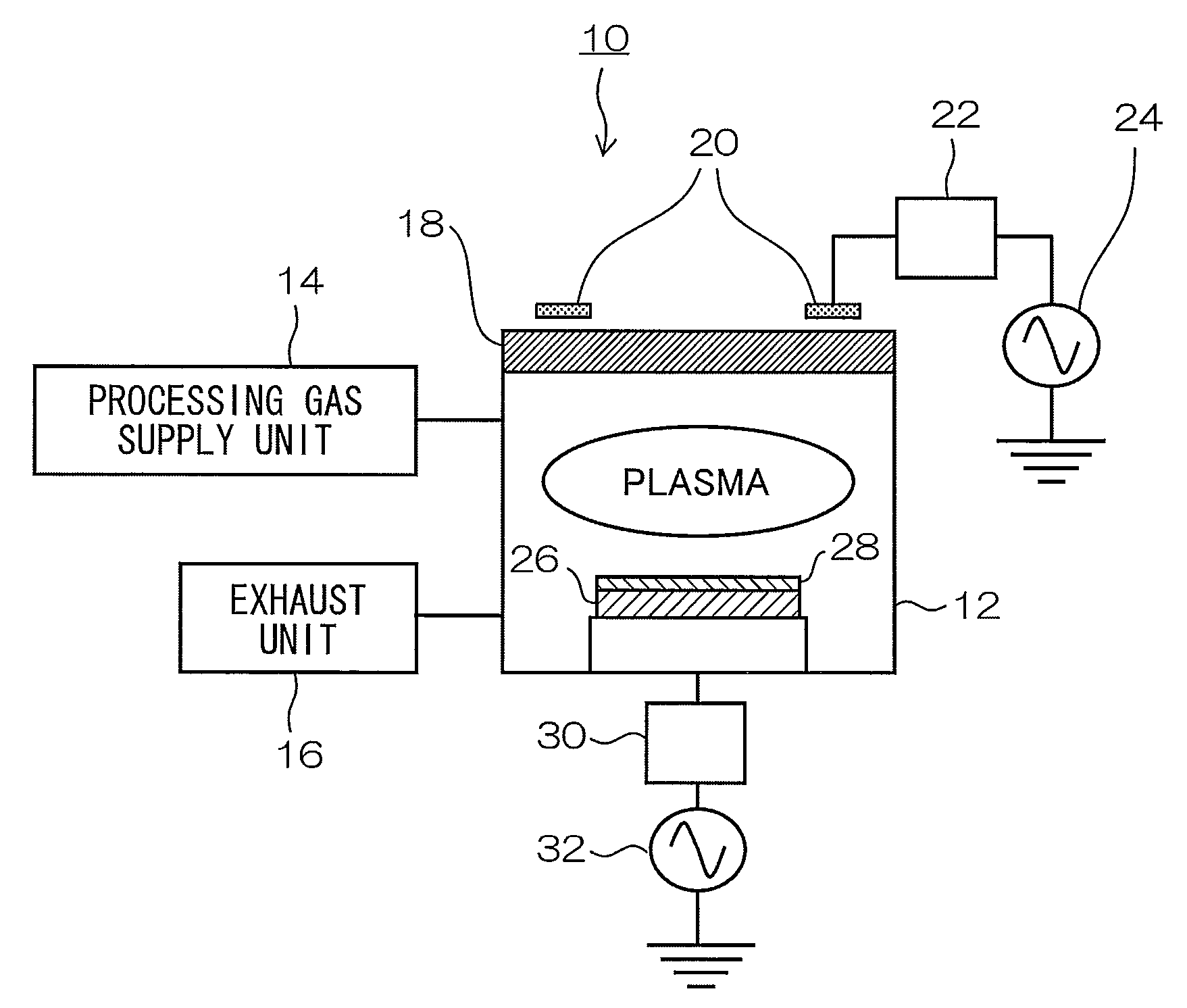
[0024]FIG. 1 is a cross-sectional view showing the general composition of a dry etching apparatus according to an embodiment of the present invention. The dry etching apparatus 10 shown in FIG. 1 includes: a vacuum chamber 12; a processing gas supply unit 14, which supplies processing gas (etching gas) to the chamber 12, an exhaust unit 16, which expels the gas from the chamber 12; and a pressure adjustment unit (not shown), which adjusts the pressure inside the chamber 12. The pressure inside the chamber 12 is adjusted by supplying the processing gas through the processing gas supply unit 14 to the chamber 12, while expelling the gas through the exhaust unit 16. As described hereinafter, a gas mixture of a plurality of fluorochemical gases is used as the processing gas in the present embodiment.

[0025]A dielectric window 18 is hermetically arranged on the upper surface of the chamber 12, and a loop antenna 20 is arranged on the upper side (the atmosphere side) of the dielectric wind...


PUM

PropertyMeasurementUnit
Frequencyaaaaaaaaaa
Frequencyaaaaaaaaaa
Ratioaaaaaaaaaa

Abstract

The dry etching method of performing etching, includes the steps of: supplying a processing gas which is a gas mixture of a plurality of fluorochemical gases; and generating plasma under a high vacuum while supplying the processing gas and applying a low-frequency bias voltage.

Description

BACKGROUND OF THE INVENTION[0001]1. Field of the Invention[0002]The present invention relates to a dry etching method and a dry etching apparatus, and more particularly to a dry etching method and a dry etching apparatus using a gas mixture of a plurality of fluorochemical gases as a processing gas.[0003]2. Description of the Related Art[0004]In general, when using dry etching to process material that is not readily etchable, such as ferroelectric substances used in piezoelectric elements and ferroelectric memory (FeRAM) and precious metals used as electrodes in these elements, it is common to use as the processing gas a gas mixture of an inert gas (e.g., argon) and a gas containing a halogen (e.g., fluorine or chlorine).[0005]Japanese Patent Application Publication No. 2006-294846 discloses a dry etching method for a ferroelectric body used in a piezoelectric element, or the like, in which a gas mixture of an inert gas and a fluorocarbon gas is used as the etching processing gas, a...

Claims


Application Information

Patent Timeline
IPC IPC(8): B44C1/22C23F1/08H01L21/3065H01L21/8246H01L27/105H01L41/09H01L41/18H01L41/22H01L41/332
CPCH01L41/332H01J37/32706H10N30/082
Inventor TAKAHASHI, SHUJI
Owner FUJIFILM CORP
Why Eureka
Try Eureka