Drying method of formed ceramic article

Inactive Publication Date: 2009-09-24
NGK INSULATORS LTD
View PDF9 Cites 29 Cited by
  • Summary
  • Abstract
  • Description
  • Claims
  • Application Information

AI Technical Summary

Benefits of technology

[0023]In the drying method of the formed ceramic article according to the present invention, when the formed ceramic article has a large moisture content, first the dielectric drying is performed, because an electromagnetic wave is easily deeply penetrated and the dielectric drying is suitable for uniform drying. On the other hand, in a case where the formed ceramic article which starts to be dried has a large moisture content, the microwave drying is not performed, because the electromagnetic wave is not easily deeply penetrated, and a difference in the moisture content between the vicinity of the surface and the inside is easily made. Therefore, even the large formed ceramic article having a large moisture content can evenly be dried without causing any crack or deformation. That is, a large dry formed ceramic article having a high quality can be obtained with a high yield.
[0024]In the drying method of the formed ceramic article according to the present invention, first the dielectric drying is performed. After the moisture content of the formed ceramic article lowers, even when little moisture is contained, the output of the electromagnetic wave does not lower, and the moisture is present. In this case, the microwave drying is performed, because the moisture can be absorbed. On the other hand, when the drying proceeds and the formed ceramic article has a small moisture content, the dielectric drying is not performed, because with the rise of impedance, the voltage (the output) is restricted. Therefore, the formed ceramic article can efficiently and completely be dried for a short time.
[0025]In a preferable configuration of the drying method of the formed ceramic article according to the present invention, after performing the microwave drying, the hot air drying is further performed. Therefore, as compared with a case where the article is completely dried (until the moisture content reaches 0 mass %) by the dielectric drying or the microwave drying, a cost required for

Problems solved by technology

However, in the natural drying method, much time is required to obtain a sufficiently dry state.
Therefore, especially when the formed honeycomb article is large, there has been a problem that a considerably long period is required to dry the article.
However, there has been a problem that cracks are easily generated, thereby incurring the lowering of quality or yield.
In the dielectric drying method, when the drying proceeds and the moisture of the formed honeycomb article decreases, impedance rises, voltage also rises, and discharge breakdown or dielectric breakdown might occur between the electrodes or in a h

Method used


Image

  • Drying method of formed ceramic article
  • Drying method of formed ceramic article
  • Drying method of formed ceramic article

Examples


example 1

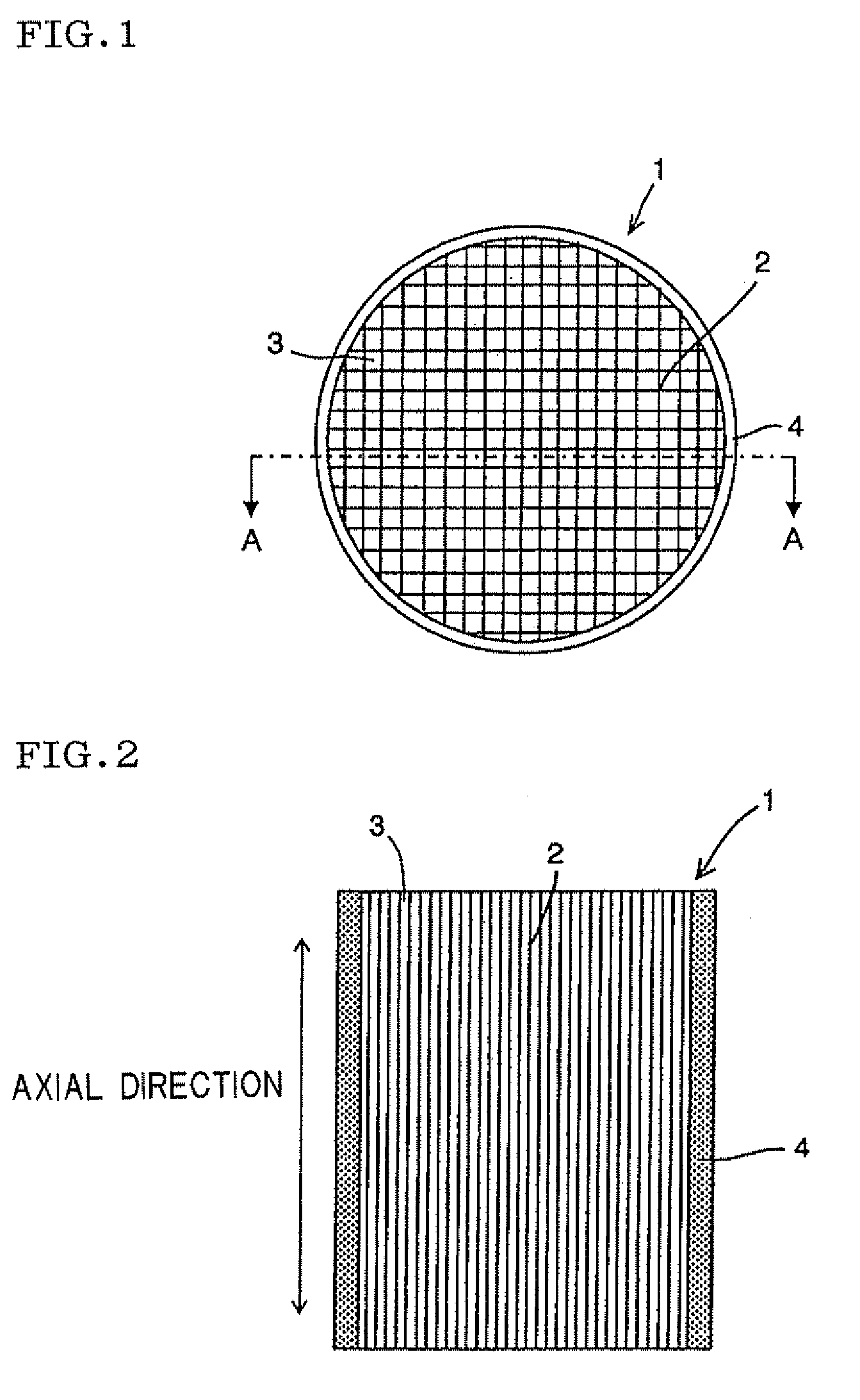
[0063][Formed Honeycomb Article] As a ceramic material, a cordierite material mixed with alumina, kaolin and talc was used, mixed with a binding material including an organic binder, a pore former and water (33 mass %) as a dispersion medium, and kneaded to obtain a kneaded clay. The resultant kneaded clay was extrusion-formed to obtain a formed honeycomb article having a diameter of 430 mm, a length (an axial length) of 600 mm, a columnar outer shape and a square sectional shape crossing the central axis of each cell at right angles. The resultant formed honeycomb article had a cell density of 300 cells / in2 (in is inch and 2.54 cm in terms of SI unit), a partition wall thickness of 310 μm and a mass of 58 kg.

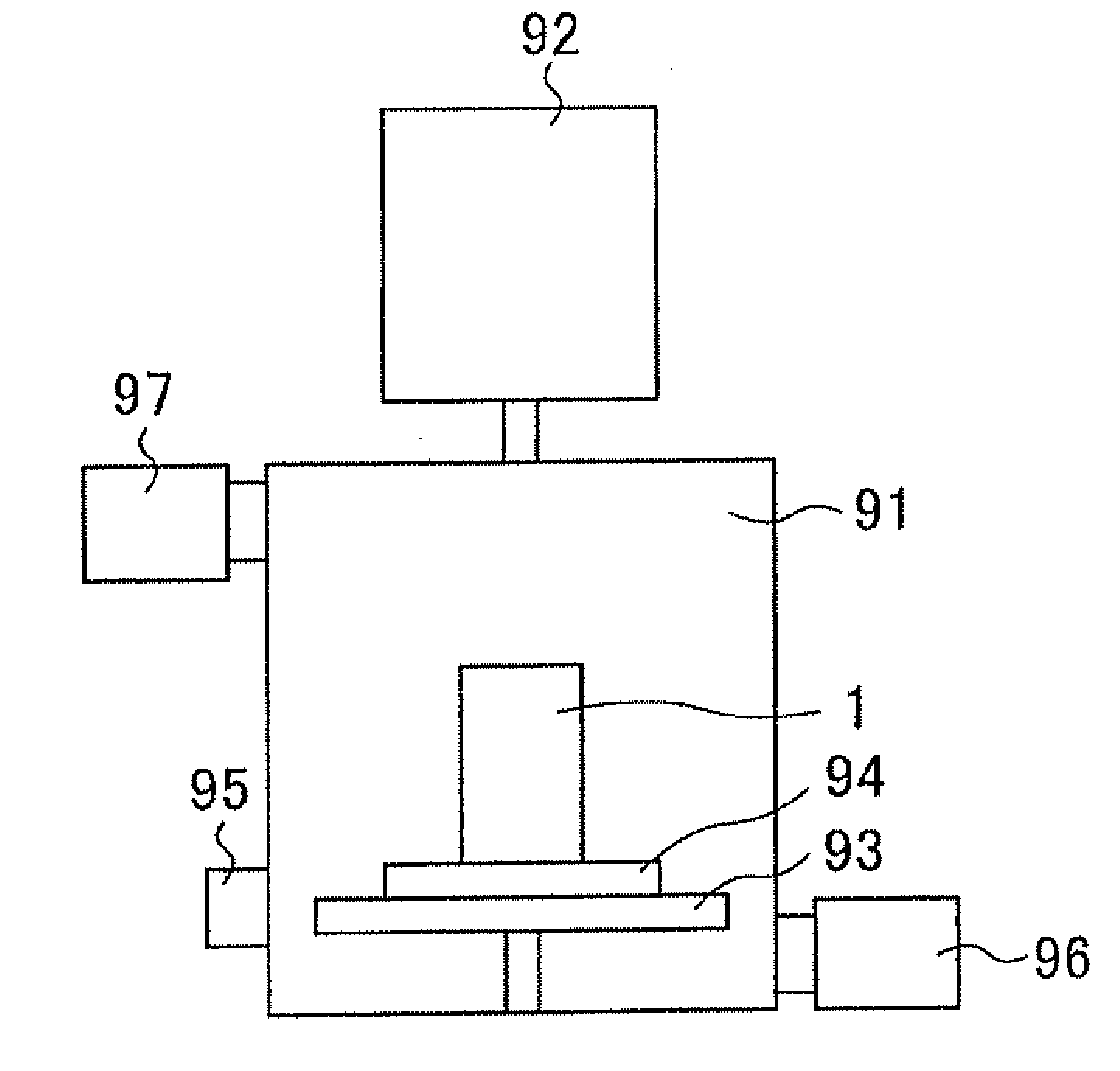
[0064][Drying Method] The resultant formed honeycomb article was subjected to batch dielectric drying by use of a dielectric drying device shown in FIG. 8 with a frequency of 13 MHz and an output of 10 kW for a heating time of 30 minutes. The dielectric drying device shown in F...

examples 2 , 3

Examples 2, 3, Comparative Examples 1 to 4

[0069]One or both of the formed honeycomb article specifications and the drying method were changed. In conformity to Example 1, formed honeycomb articles were prepared and dried, moisture contents were measured, and evaluations were also performed. The results of the evaluations are shown together with the specifications of the formed honeycomb articles, drying methods and moisture contents after the drying in Table 1.

TABLE 1Formed honeycombDrying methodsarticleOutput [kW]Heating time [min.]Moisture content [%]EvaluationDiameter ×Micro-Micro-AfterAfterSelflengthMassDielectricwaveDielectricwavedielectricmicrowaveigni-[mm][kg]StepdryingdryingdryingdryingdryingdryingCrackDischargetionExample 1φ430 × 60058Microwave10243030264NoneNoneNonedrying afterdielectricdryingExample 2φ430 × 60058Microwave10246012.5175NoneNoneNonedrying afterdielectricdryingExample 3φ290 × 60021Microwave1024187.5204NoneNoneNonedrying afterdielectricdryingComparativeφ430 × ...


PUM

PropertyMeasurementUnit
Percent by massaaaaaaaaaa

Abstract

There is disclosed formed ceramic article drying means capable of evenly and uniformly drying even a large formed ceramic article containing much moisture as a drying target for a short time without causing any crack or deformation, to efficiently obtain a dry formed ceramic article having a high quality with a satisfactory yield. There is provided a drying method of a formed ceramic article including the steps of subjecting an unfired formed ceramic article formed of a ceramic material as a main material to dielectric drying and then microwave drying.

Description

BACKGROUND OF THE INVENTION[0001]1. Field of the Invention[0002]The present invention relates to a drying method of a formed ceramic article having a large moisture content.[0003]2. Description of the Related Art[0004]A ceramic honeycomb structure is broadly used in a catalyst carrier, various filters and the like. In recent years, the ceramic honeycomb structure attracts attention especially as a diesel particulate filter (DPF) for collecting a particulate matter (PM) discharged from a diesel engine.[0005]Such a honeycomb structure can usually be obtained by kneading a raw material obtained by adding various additives such as water and a binder to a ceramic material to obtain a kneaded clay; preparing a formed article having a honeycomb-like shape (a formed honeycomb article) from the kneaded clay by extrusion forming; and drying and then firing this formed honeycomb article.[0006]Heretofore, as means for drying the formed honeycomb article, there have been known a natural drying m...

Claims


Application Information

Patent Timeline
IPC IPC(8): F26B7/00
CPCB28B11/241B28B11/243C04B2235/606C04B2235/6021C04B2235/5228C04B2235/428C04B2235/425C04B2235/3418C04B2235/3217C04B2111/0081C04B2111/00793C04B41/85C04B41/5089C04B41/009C04B38/0006C04B35/806C04B35/803C04B35/6316C04B35/6303C04B35/584C04B35/111C04B35/185C04B35/195C04B35/486C04B35/565C04B35/581C04B35/10C04B14/4656C04B41/5025C04B41/5024C04B35/00C04B35/80
Inventor TAKAGI, SHUICHIYOSHIDA, MASAKIHORIBA, YASUHIRO
Owner NGK INSULATORS LTD
Why Eureka
Try Eureka