Stone work simulation system

a simulation system and stone wall technology, applied in building components, climate sustainability, solid waste management, etc., can solve the problems of high cost, labor and time requirements, and high labor and time requirements for installing a simulated stone wall, facing, or facade, and the overall aesthetic appearance of the simulated system is generally not acceptabl

Inactive Publication Date: 2009-09-24
TAPCO INTERNATIONAL CORPORATON
View PDF20 Cites 43 Cited by
  • Summary
  • Abstract
  • Description
  • Claims
  • Application Information

AI Technical Summary

Benefits of technology

[0021]As described above in connection with the open mold casting process, if a color effect is intended to be imparted to the stone work simulation system, a colorant can be applied to the surface (or portions thereof) of the lower mold surface member before the mat is overlaid onto it. Alternatively, the colorant can be applied to the stone work

Problems solved by technology

This process is typically very expensive, labor intensive, and time consuming, as the natural stone products must first be sorted and arranged to form a desired pattern, and then carefully and slowly mounted onto the surface with the use of an appropriate material, such as mortar or cement.
The use of “man-made” or synthetic stone products has reduced the cost, labor, and time requirements to install a simulated stone wall, facing, or facade, but in some cases the overall aesthetic appearance of the simulated system is ge

Method used


Image

  • Stone work simulation system
  • Stone work simulation system
  • Stone work simulation system

Examples


Embodiment Construction

[0050]The following description of the preferred embodiments is merely exemplary in nature and is in no way intended to limit the invention or its uses.

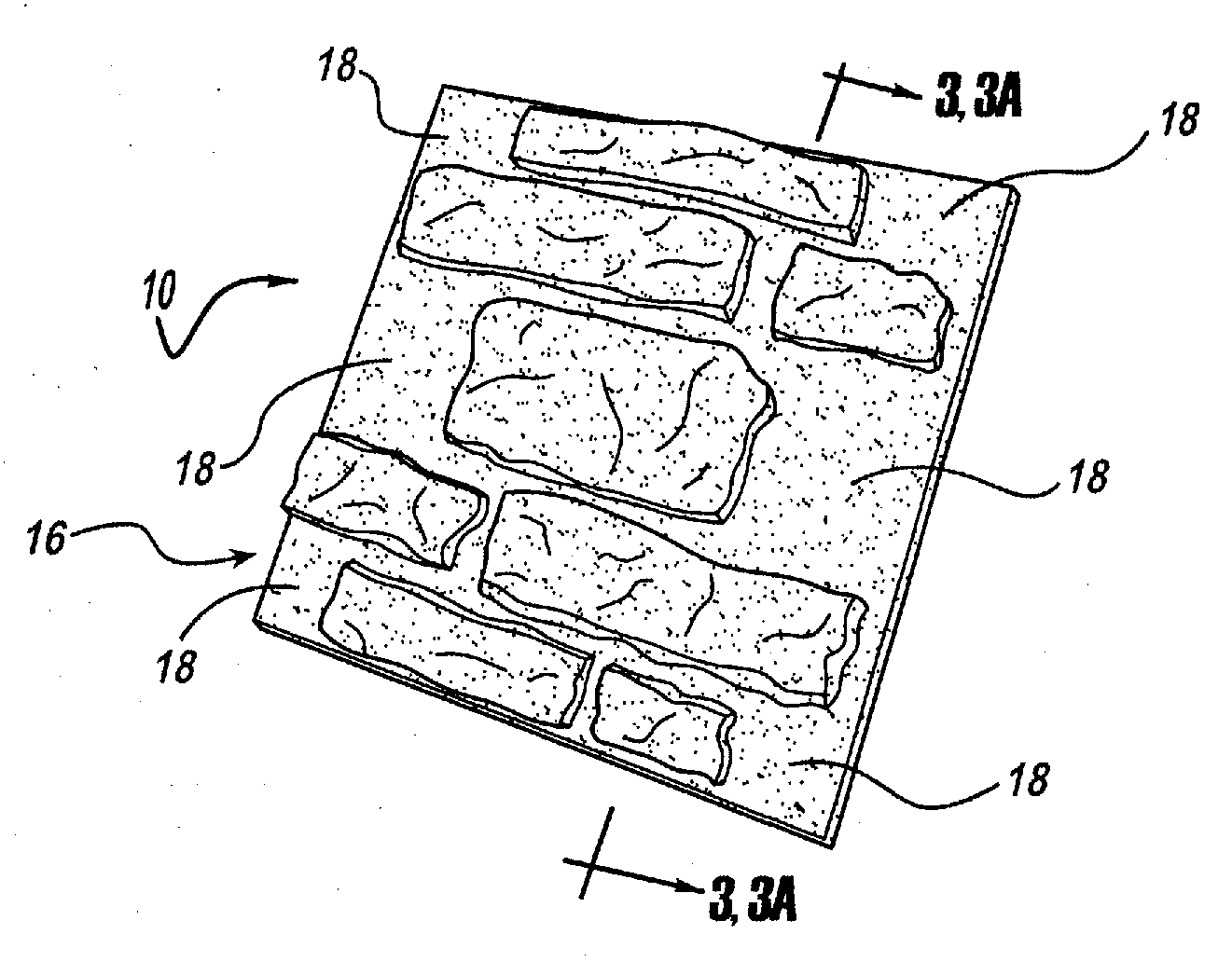
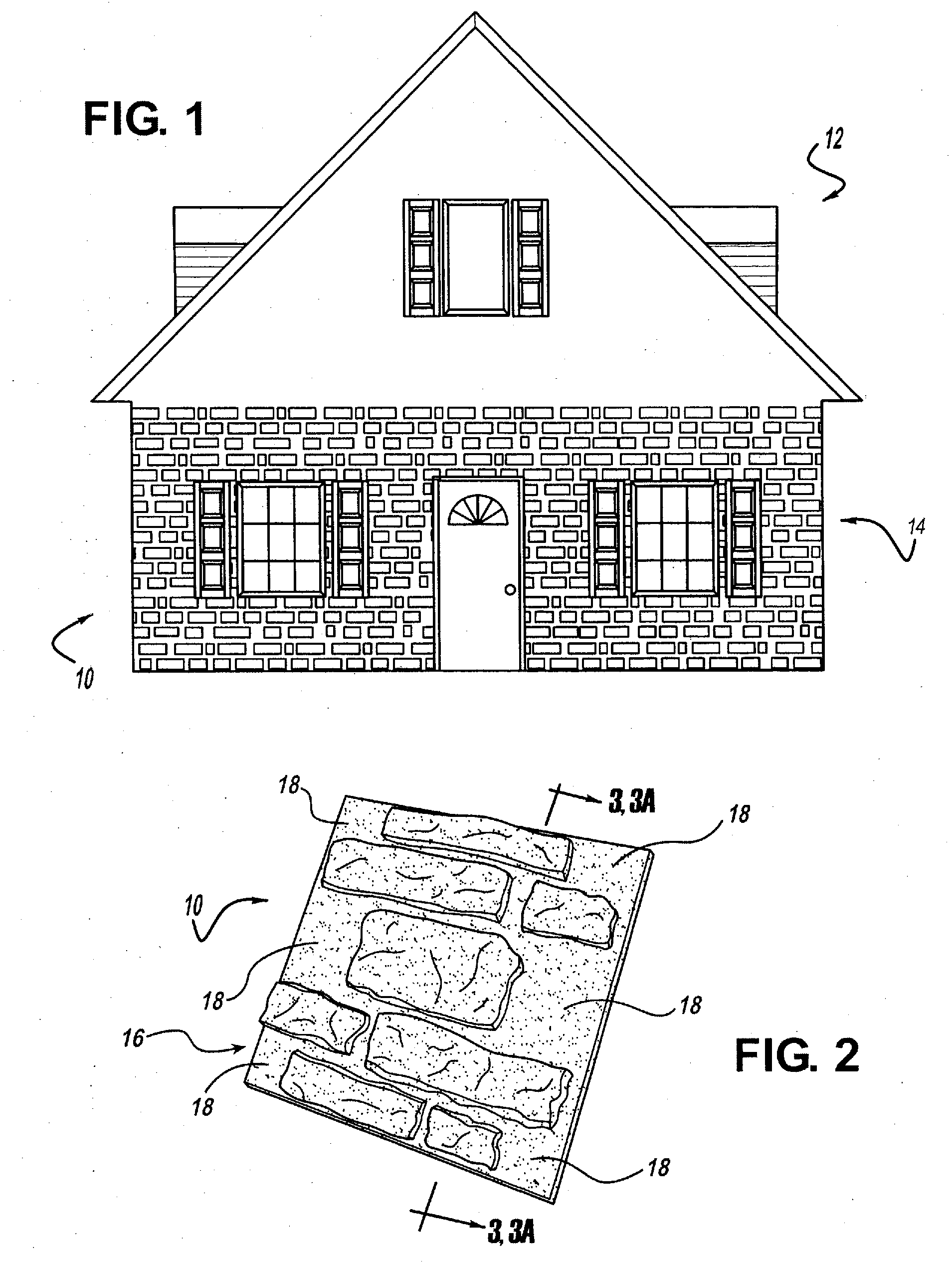
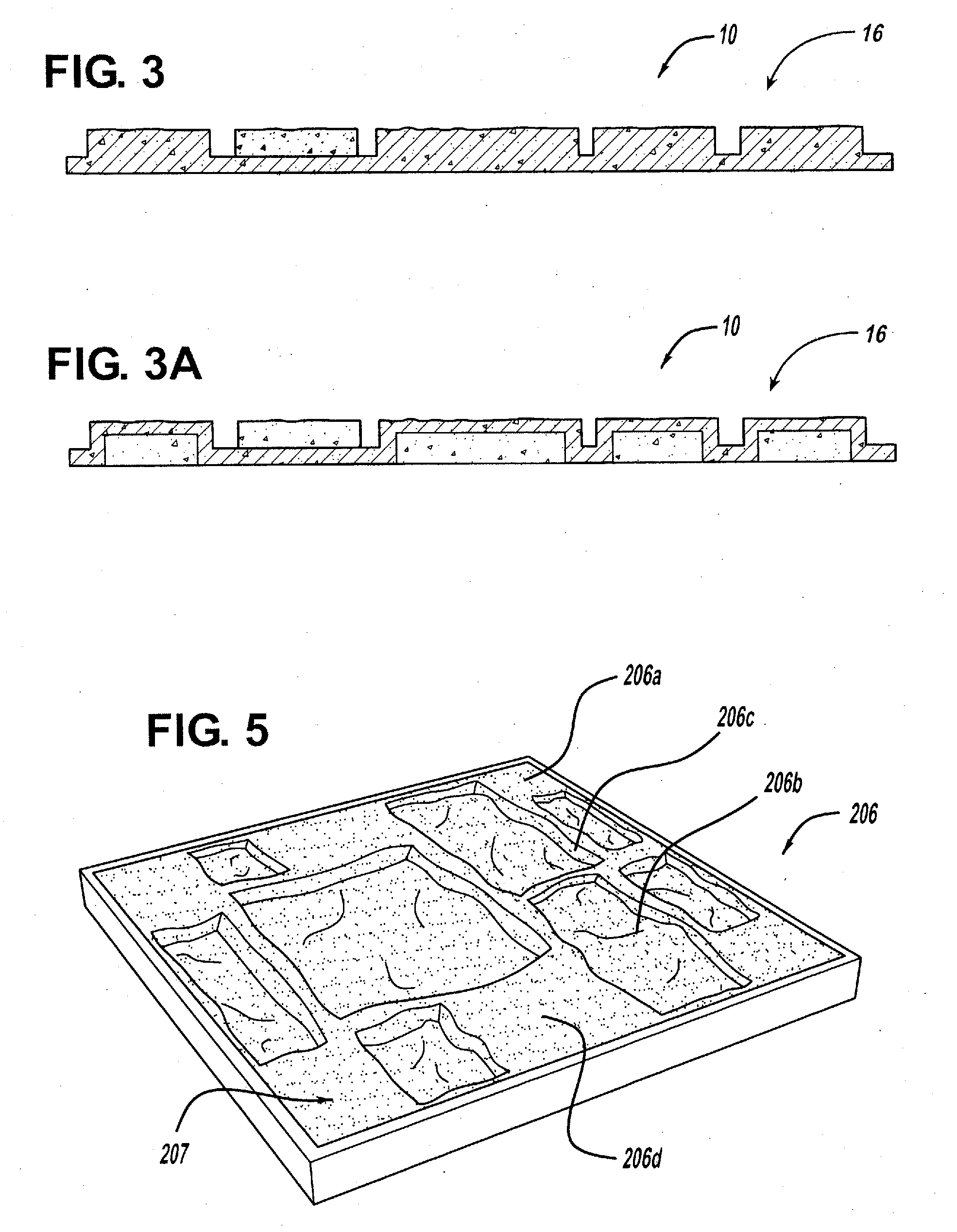
[0051]Referring to the Figures generally, and specifically to FIGS. 1-4A, a stone work simulation system is generally disclosed at 10. By “system,” as that term is used herein, it is meant at least one unit of a simulated stone, simulated brick or other simulated building material product. The system can also include one or more units of simulated stone, brick or other building material product or building product produced on a single sheet or sheet-like member, such as a panel. The system can also include one or more individual building product units (e.g., simulated stone units) that are mounted individually to a structure in conjunction with the sheet members. Although the present invention will be described with primary reference to stone work simulation systems, such as but not limited to stone or brick walls, facings, and facad...


PUM

PropertyMeasurementUnit
Thicknessaaaaaaaaaa
Coloraaaaaaaaaa
Heightaaaaaaaaaa

Abstract

A stone work simulation system including panels formed from a cementitious material. The panels of the system can be cast or injection molded from cementitious slurry, including hydraulic cement, or gypsum cement and an optional latex/water mixture. A desired amount of the slurry is added to the mold, the surface of which includes several spaced apart depressions formed therein to closely resemble a pattern of stones at least partially disposed in a mortar matrix. Optionally, the mold can include a number of flat spaces formed between the depressions. Optionally, a reinforcing mesh is also provided in the mold. A colorant can be disposed on the bottom mold surface prior to the introduction of the mesh and the slurry to impart a color pattern to the system. After sufficient curing, the panel is removed from the mold and is ready for immediate use and/or further processing, such as additional surface coloring. In use, the system can be mounted to a building surface, such as a wall, e.g., with a mechanical fastener, adhesive, mortar, cement, and/or the like. To provide distinctiveness to the system, a plurality of individual simulated stones (e.g., that have been formed separately or as a separable unit, e.g., according to the process above) that are sized, shaped, and colored similarly to or differently from the system, can be incorporated onto the flat spaces formed on the system to form a unique finished product and avoid the appearance of the installed system being an arrangement of individual panel units.

Description

CROSS REFERENCE TO RELATED APPLICATION[0001]The present application claims priority to U.S. Provisional Patent Application Ser. No. 61 / 038,632, filed Mar. 21, 2008, the disclosure of which is hereby expressly incorporated by reference in its entirety.FIELD OF THE INVENTION[0002]The present invention relates to architectural and exterior / interior decorative siding and trim elements, such as stone walls, facings, and facades, and more specifically to architectural and decorative trim elements, such as stone walls, facings, and facades, formed from cementitious slurries, especially those containing gypsum.BACKGROUND OF THE INVENTION[0003]Many different modern building designs take advantage of various architectural and decorative siding or trim elements, including stone or brick walls, facings, and facades, for purely aesthetic purposes, e.g., to decorate the interior and / or exterior surfaces. Additional architectural and decorative trim elements can also be used in conjunction with ot...

Claims


Application Information

Patent Timeline
IPC IPC(8): E04C2/30E04C2/04E04F13/14B28B1/14
CPCB28B7/0073B28B7/36B28B13/0275B28B23/0006C04B28/14C04B28/146C04B28/147C04B2111/54E04F13/147C04B7/02C04B14/42C04B16/0633C04B16/0675C04B16/0691C04B18/08C04B22/124C04B24/2641C04B24/305C04B40/0067C04B40/0259Y02W30/91
Inventor LOGAN, JOHN RICHARDBAKER, THOMAS J.
Owner TAPCO INTERNATIONAL CORPORATON
Why Eureka
Try Eureka