Inverter

a technology of inverters and inverters, which is applied in the direction of electric generator control, dynamo-electric converter control, dynamo-electric gear control, etc., can solve the problems of low-order distortion of input current, difficulty in separating both inverter sections from each other, and increase in volume and cost of inverter sections, so as to achieve stable operation, speed control is easy to perform, and the attenuation coefficient is increased.

Active Publication Date: 2009-09-24
DAIKIN IND LTD
View PDF8 Cites 16 Cited by
  • Summary
  • Abstract
  • Description
  • Claims
  • Application Information

AI Technical Summary

Benefits of technology

[0018]According to the above embodiment, the inverter section is vector-controlled by the control section, and therefore, speed control can easily be performed with stable operation.
[0019]As is apparent from the above, according to the inverter of the invention, in the inverter having the LC filter in the DC link part, the distortions of the input current can be suppressed with vibrations suppressed, and the vibration suppression is performed on the basis of the cross terminal voltage of the inductance element. Therefore, the output current set point of the diode bridge becomes a direct current, and control becomes possible without interference with the resonance frequency of the LC filter.
[0020]Moreover, according to the inverter of one embodiment, the attenuation coefficient is increased by controlling the input current of the inverter section by the control section on the basis of the cross terminal voltage of the inductance element detected by the voltage detecting section, and stability is improved by making the control system have a characteristic close to the first-order lag system by gain setting corresponding to the constant of the reactance element of the LC filter.
[0021]Moreover, according to the inverter of one embodiment, the attenuation coefficient is increased by controlling the voltage control ratio of the inverter section by the control section on the basis of the cross terminal voltage of the inductance element detected by the voltage detecting section, and stability is improved by making the control system have a characteristic close to the first-order lag system by gain setting corresponding to the constant of the reactance element of the LC filter. In addition, the relation between the AC load current and the DC load current can be directly controlled by the voltage control ratio, a high-speed response can be achieved, and more stable operation becomes possible.
[0022]Moreover, according to the inverter of one embodiment, the inverter section is vector-controlled by the control section, and therefore, speed control can easily be performed with stable operation.

Problems solved by technology

In this case, the smoothing circuit needs large-scale capacitor and reactor for smoothing voltage pulsations at the commercial frequency, and this therefore causes an increase in volume and a cost increase of the inverter section.
Accordingly, it is difficult to separate both of them from each other, and there is a problem that low-order distortions occur in the input current as a consequence of the smoothing of the DC voltage.

Method used


Image

  • Inverter
  • Inverter
  • Inverter

Examples


first embodiment

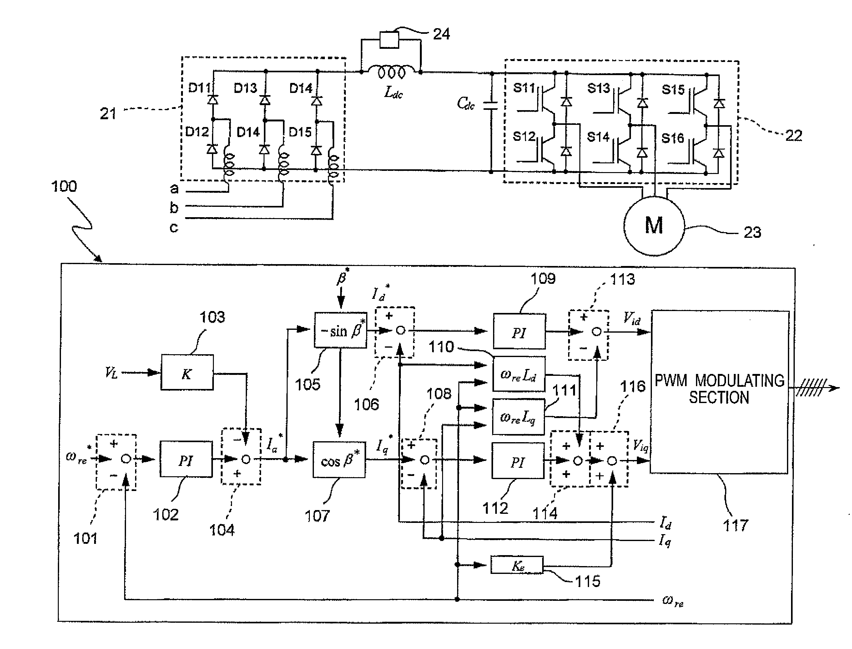
[0094]FIG. 18 shows a block diagram of the inverter of the first embodiment of the invention.

[0095]As shown in FIG. 18, the inverter has a diode bridge 21 constructed of six diodes D11 through D16 that constitute a three-phase diode bridge circuit, an inverter section 22 constructed of six switching elements S11 through S16 that constitute a three-phase bridge circuit, and a control section 100 that controls the inverter section 22. Moreover, the inverter has an inductor Ldc as one example of the inductance element connected between the positive pole side output terminal of the diode bridge 21 and the positive pole side input terminal of the inverter section 22, a capacitor Cdc as one example of the capacitance element connected across the input terminals of the inverter section 22, and a voltage detecting section 24 that detects the cross terminal voltage VL Of the inductor Ldc. The inductor Ldc and the capacitor Cdc constitute an LC filter. A three-phase AC voltage from a three-ph...

second embodiment

[0115]FIG. 19 shows a block diagram of the inverter of the second embodiment of the invention. The inverter has a construction identical to that of the inverter of the first embodiment except for the control section.

[0116]The control section 200 of the inverter has:

[0117]an adder-subtractor 101 that subtracts the rotational angular velocity ωre from the rotational angular velocity set point ωre* and outputs a difference signal;

[0118]a PI controller 102 that performs PI control of a difference signal from the adder-subtractor 101;

[0119]a multiplier 103 that multiplies the cross terminal voltage VL of the inductor Ldc, detected by the voltage detector 24 by the gain k;

[0120]a conversion section 105 that multiplies the current set point Ia* from the PI controller 102 by −sin β* (β*: current phase set point) and outputs a d-axis current set point Id*;

[0121]an adder-subtractor 106 that subtracts the d-axis current value Id from the d-axis current set point Id* from the conversion section...


PUM


Abstract

The inverter comprises a diode bridge (21) that rectifies an inputted three-phase AC voltage into a DC voltage, an inverter section (22) that converts the DC voltage converted by the diode bridge (21) into an AC voltage and outputs the resulting voltage, an LC filter that has an inductor Ldc connected between one output terminal of the diode bridge (21) and one input terminal of the inverter section and a capacitor Cdc connected across the input terminals of the inverter section, a voltage detecting section (24) that detects cross terminal voltage of the inductor Ldc, and a control section (100) that controls the inverter section (22). The control section (100) controls the inverter section (22) so that the transfer characteristic of the I/O voltage of the inverter section (22) becomes a characteristic of the first-order lag system on the basis of the cross terminal voltage of the inductor Ldc detected by the voltage detecting section (24).

Description

TECHNICAL FIELD[0001]The present invention relates to inverters, and in particular, to an inverter that has an LC filter for suppressing only a carrier current component in a DC link part between a diode bridge and an inverter section.BACKGROUND ART[0002]Conventionally, as a typical inverter main circuit construction, a construction for once converting a commercial alternating current into a DC voltage via a rectifying circuit and a smoothing circuit and obtaining an AC voltage by a voltage-fed inverter section is generally employed. In this case, the smoothing circuit needs large-scale capacitor and reactor for smoothing voltage pulsations at the commercial frequency, and this therefore causes an increase in volume and a cost increase of the inverter section. Therefore, a main circuit construction for compacting the LC filter and suppressing only the carrier current component of the inverter is proposed. (Refer to, for example, “3. Direct AC power converter circuit (present conditi...

Claims


Application Information

Patent Timeline
Patent Type & Authority Applications(United States)
IPC IPC(8): H02M5/44H02M7/48H02P21/00H02P21/05H02P21/22H02P23/04H02P23/16H02P27/04H02P27/06
CPCH02M5/458Y02B70/145H02P21/0035H02M1/15H02P21/0003H02P27/08H02P21/22Y02B70/10H02M7/48H02P21/00H02P27/06
Inventor SAKAKIBARA, KENICHIHAGA, HITOSHI
Owner DAIKIN IND LTD
Why Eureka
Try Eureka