
Method and Apparatus for Absolute-Coordinate Three-Dimensional Surface Imaging

a three-dimensional surface and absolute-coordinate technology, applied in image analysis, instruments, computing, etc., can solve the problems of affecting the speed of further processing, affecting the accuracy of the image, and providing a relatively small measurement error, so as to achieve the effect of convenient display and manipulation

Inactive Publication Date: 2009-09-24
HANGZHOU CONFORMAL & DIGITAL TECH CORP
View PDF8 Cites 178 Cited by
  • Summary
  • Abstract
  • Description
  • Claims
  • Application Information

AI Technical Summary

Benefits of technology

"The present invention provides an apparatus for absolute coordinate 3D surface measurement that is simple and portable. It eliminates the need for complex setup and sensors. The apparatus uses two phase-shifted illumination patterns and a camera to capture the reflections of the patterns from the surface of an object. The patterns are projected in a repeating sequence and captured as a wrapped phase image. An absolute phase map is obtained by detecting the small marker in each of the patterns and using a quality map with multiple quality levels. The absolute coordinates of the object are determined using a GPU-assisted method. The invention allows for real-time capture of moving objects and flexible image manipulation and processing."

Problems solved by technology

More than three fringe patterns have been used in practice as well, which however impedes the speed of further processing.
The phase shift δ may vary from one application to another, but experiments demonstrated that a phase shift of 120 degrees provides a relatively small measurement error, as described in the prior art.
Moreover, using this algorithm may reduce computational errors associated with motion of the object.
Moreover, a color of the object may potentially be difficult to distinguish from the colors of the illumination patterns, which can interfere with a quality of measurement.
However, for purposes of facial recognition, image generation and related computer graphics applications, the texture is used to create an appearance of complexity on the surface by mapping relatively fine details of the surface obtained from a (usually) 2D image into a related 3D space.
Unfortunately, the recovered phase determined using Eq.
However, such quality-guided algorithms typically involve a time-consuming point-by-point sorting, which makes it difficult to achieve real-time performance at reasonable cost.
Other algorithms exist that are able to perform phase unwrapping rapidly, but they do not provide sufficient accuracy.
Larger numbers of levels can be used as well, but the greater the number of levels used, the slower the processing speed.
The process of smoothing out phase transitions at discontinuities by comparison with neighbor pixels is somewhat inefficient.
However, increasing the number of images used to reconstruct the 3D geometry decreases the measurement speed.
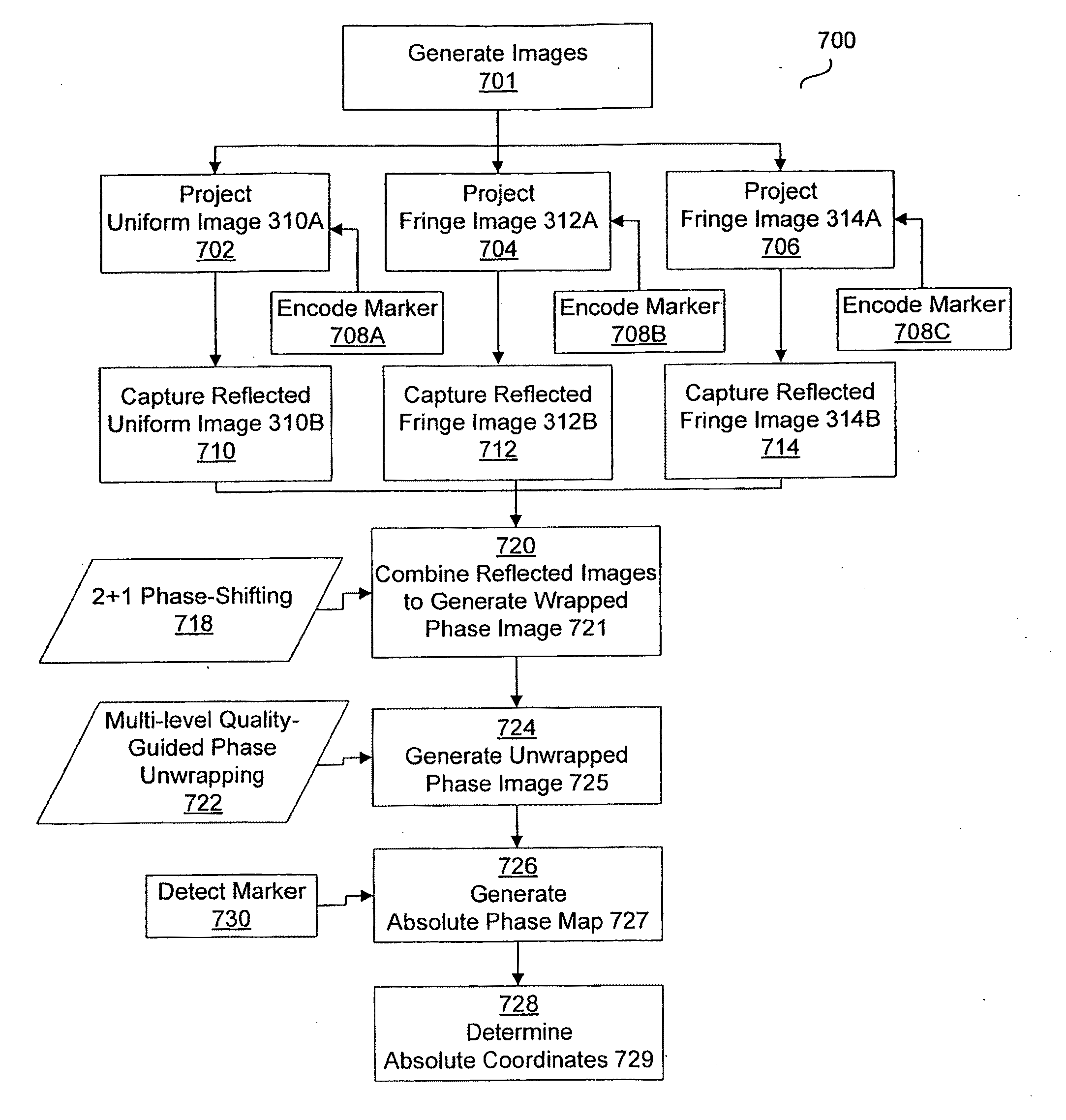
However, locating the small marker in a 2D image is generally difficult, especially if the image is blurred. FIG. 17 shows an example of detection of the marker.
However, in general, detecting the marker from the gamma map is also difficult.
If all of the computations are done by the CPU, the real-time reconstruction and display will be difficult to achieve on an ordinary desktop computer.
(It should be understood that the projection angle of 80° was a “generated” angle in a computer implementation and that such a large projection angle is probably not practical in an optical projection system since some features of the subject object, a head, would occlude other features or areas.
Common 24-bit image formats thus are good enough for storing the geometric information in a holoimage, which is not possible for geometry images.
Although it is easy to capture image textures, it is generally difficult to capture geometric textures.
The capture of phase information to represent 3D surfaces is of limited value without a way to store an image representation.
However, there are also limitations to the optical-camera system that are not present in the computer-camera system.
1. Occlusion—A holoimage can only represent the visible part of a surface. In order to represent the whole surface, multiple holoimages are required.
2. Materials Limits—For 3D data acquisition, dark or glossy materials can not be captured accurately.

Method used


Image

  • Method and Apparatus for Absolute-Coordinate Three-Dimensional Surface Imaging
  • Method and Apparatus for Absolute-Coordinate Three-Dimensional Surface Imaging
  • Method and Apparatus for Absolute-Coordinate Three-Dimensional Surface Imaging

Examples


Embodiment Construction

[0067]The invention and its advantages will be readily apparent to those skilled in the art from the following description of some prior art and embodiments of practicing the invention, which are given by way of example only, with reference to the accompanying drawings.

Prior Art Method and Apparatus for 3D Surface Contouring

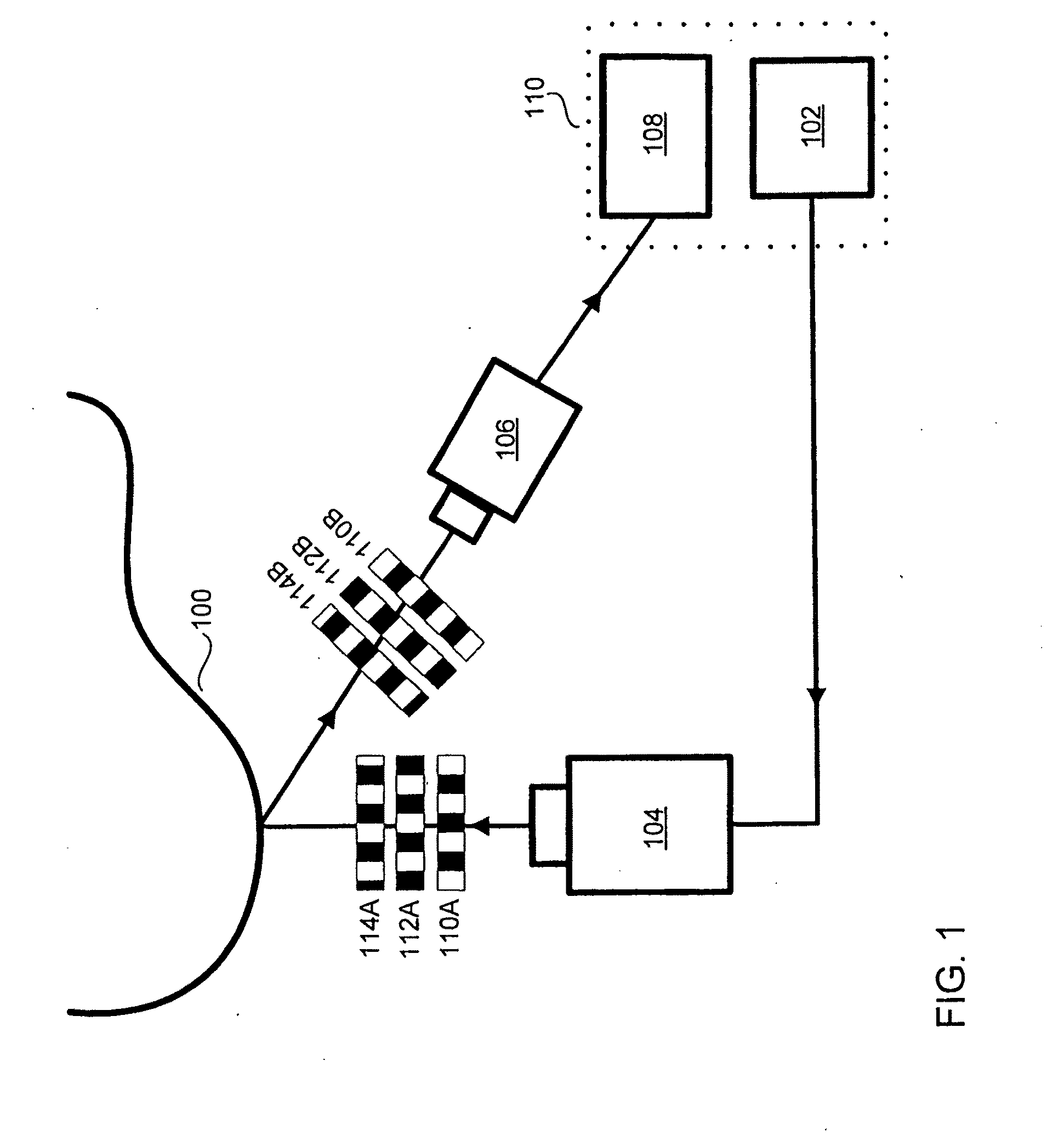
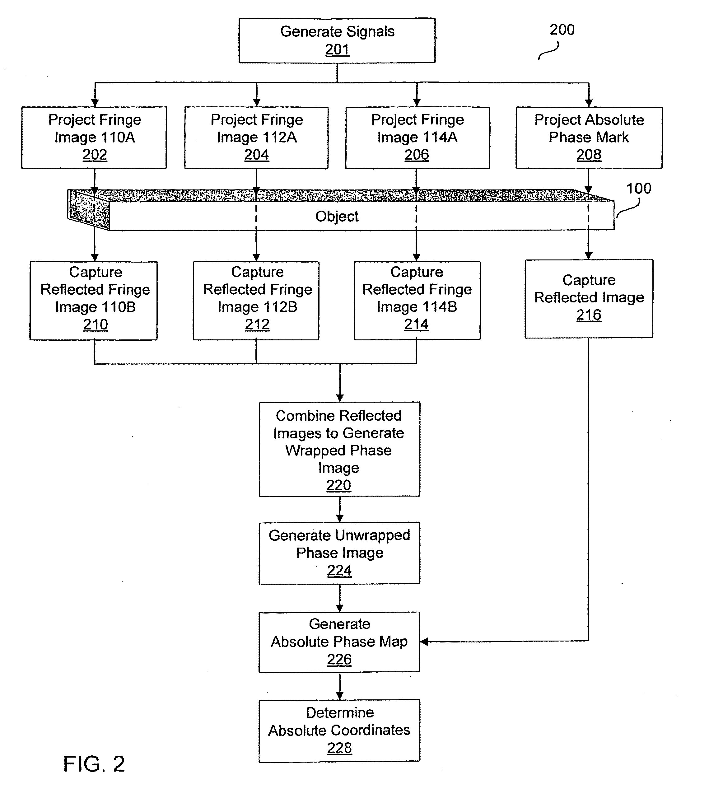
[0068]Referring to FIG. 1, a setup for a prior art system for 3D surface measurement is shown schematically. A signal generator 102 drives a projector 104 to illuminate a surface of an object 100. A camera 106 receives the corresponding reflected images and delivers them to an image processor 108. The image processor 108 derives the objects' surface contour from the reflected images.

[0069]As shown in FIG. 1, signal generator 102 and image processor 108 can be (and usually are) located within the same device 110, such as a personal computer, workstation, processor, or other device. For example, the signal generator and image processor may comprise separate softwar...


PUM


Abstract

A method and associated apparatus for capturing an image of a 3D object (100) which encodes the surface geometry of at least a portion of the object, comprising: 1. projecting (304) a plurality of fringe patterns (312A, 314A) onto the object; 2. capturing (306) phase alterations in reflections of the fringe patterns (312B, 314B) from the object; 3. projecting a uniform image (310A) onto the object; 4. capturing a reflection of the uniform image (310B) from the object; and 5. combining (310) captured phase alterations and captured uniform image reflection on a pixel-by-pixel basis, thereby forming a holoimage representation of the object.

Description

CROSS-REFERENCE TO RELATED APPLICATIONS[0001]This applications claims the benefit, under 35 USC 119(e) of provisional U.S. Patent Application 60 / 734,749, filed Nov. 9, 2005 by Gu et al and titled “Holoimage,” and of provisional U.S. Patent Application 60 / 841,840, filed Sep. 1, 2006 by Zhang and titled “3D Camera System and Method,” which are hereby incorporated by reference in their entirety.FIELD OF THE INVENTION[0002]The present invention relates generally to a method and apparatus for absolute-coordinate three-dimensional surface imaging. More particularly, it relates to improved phase wrapping and unwrapping of an optical image to obtain surface contours. It further provides a novel method for creating, representing, storing and manipulating 3D geometric surfaces and images.BACKGROUND OF THE INVENTION[0003]The capture and representation of 3D geometric surface images is central to a number of image processing tasks, from animation to moviemaking to medical imaging. The tradition...

Claims


Application Information

Patent Timeline
Patent Type & Authority Applications(United States)
IPC IPC(8): G06K9/00
CPCG06T7/0057G01B11/2536G06T7/521
Inventor ZHANG, SONGYAU, SHING-TUNGGU, XIANFENGWANG, YALINROYER, DALE
Owner HANGZHOU CONFORMAL & DIGITAL TECH CORP
Learn More