Distillation method and apparatus

a technology of distillation method and apparatus, which is applied in the direction of lighting and heating apparatus, refrigeration and liquid storage, and solidification. it can solve the problems of increasing electrical power consumption, inability to produce constant product slate of liquid and gaseous products from air separation plants, and inability to meet the needs of liquid and gaseous products. it achieves a high production rate and the effect of increasing the expansion ratio

Inactive Publication Date: 2009-10-01
PRAXAIR TECH INC
View PDF18 Cites 24 Cited by
  • Summary
  • Abstract
  • Description
  • Claims
  • Application Information

AI Technical Summary

Benefits of technology

[0020]The turbine booster compression system has a first booster compressor coupled to the turboexpander, a second booster compressor and a flow control network having valves operable to be set into positions such that at a low rate of production of the at least one liquid product stream, part of the compressed feed stream is compressed within the first booster compressor, thereby to further compress the second compressed stream. During a high rate of production of the at least one product stream, the second booster compressor is coupled to the first booster compressor so that the part of the compressed feed stream is compressed to a pressure higher than that obtainable by the first booster compressor, thereby to further compress the second compressed stream and to increase the expansion ratio across the turboexpander and the refrigeration generated by the turboexpander.
[0021]A variable speed drive drives the second booster compressor such that varying the speed of the variable speed drive varies the pressure of the second compressed stream and therefore production of the at least one liquid product stream during the high rate of production.

Problems solved by technology

However, as is also known, this consumes more electrical power in driving the booster compressor that feeds compressed air to the turboexpander.
Moreover, the demand for liquid products is very often variable and as such, a constant product slate of liquid and gaseous products from an air separation plant is not desired.
As can be appreciated, an air separation plant such as described above cannot be designed to efficiently operate at both a high rate of liquid production and a low rate of liquid production given the fact that rotating compression and turbine equipment on a single gear case have narrow operation ranges at which they can efficiently operate.

Method used


Image

  • Distillation method and apparatus
  • Distillation method and apparatus
  • Distillation method and apparatus

Examples


Embodiment Construction

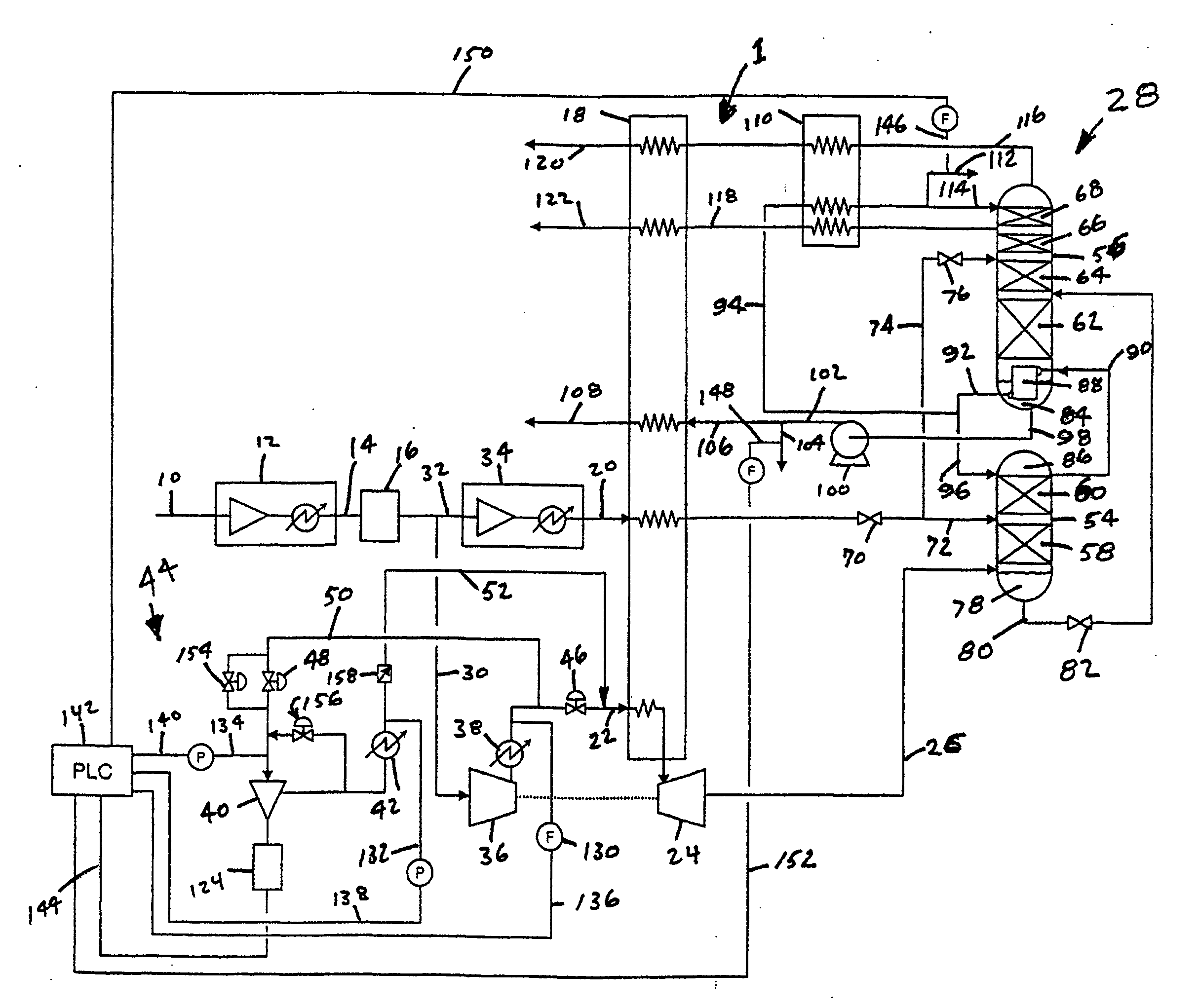
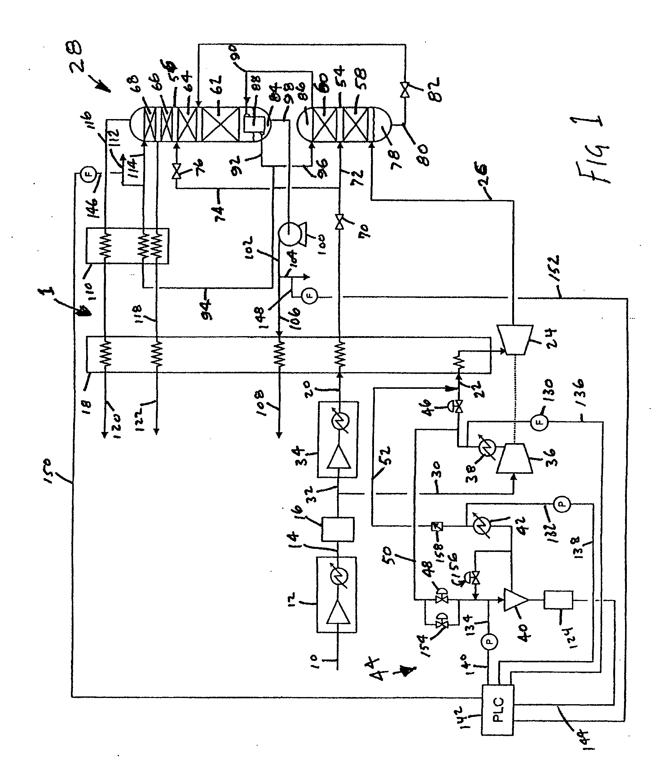
[0030]A feed stream 10 containing oxygen and nitrogen, for instance air, is distilled within a distillation apparatus 1 in accordance with the present invention. Distillation apparatus 1 is designed to produce gaseous and liquid oxygen products as well as gaseous nitrogen and liquid products. It is understood, however that this is for purposes of illustration only and the present invention has applicability to a distillation apparatus in which only a single column is used to produce gaseous and liquid nitrogen products such as in a nitrogen generator as has been described above. Additionally, although not illustrated, a distillation apparatus and method in accordance with the present invention might also include other columns that, for example, are specifically designed for argon and rare gas production.

[0031]Feed stream 10 is compressed within a base load compressor 12 that may be an intercooled, integral gear compressor with condensate removal. The resultant compressed feed stream...


PUM


Abstract

A distillation method and apparatus having application to the distillation of air in which liquid production make is varied by varying the pressure ratio across a turboexpander used in generating refrigeration. The pressure ratio is varied by varying the pressure of a compressed stream fed to the turboexpander. This is done by solely compressing such compressed stream by a first booster compressor during a low rate of production of liquid products. During a high rate of production of liquid products, the compressed stream is also compressed within a second booster compressor. The second booster compressor is driven by a variable speed drive to allow a variety of liquid production rates between the low level of liquid production and the high level of liquid production.

Description

FIELD OF THE INVENTION[0001]The present invention relates to a distillation method and apparatus in which an oxygen and nitrogen containing feed is rectified by a cryogenic rectification process to produce at least liquid oxygen and / or liquid nitrogen products in addition to gaseous oxygen and / or gaseous nitrogen products. More particularly, the present invention relates to such a method and apparatus in which a variable speed booster compressor is utilized to vary production of the liquid products between a high rate and a low rate of liquid production.BACKGROUND OF THE INVENTION[0002]Oxygen and nitrogen containing mixtures are distilled within one or more distillation columns of an air separation plant. In such a plant, the feed stream is typically compressed and then cooled within a main heat exchanger to a temperature suitable for its distillation. The resultant cooled stream is then separated into its component parts through rectification within a distillation column system.[00...

Claims


Application Information

Patent Timeline
Patent Type & Authority Applications(United States)
IPC IPC(8): F25J3/04
CPCF25J3/04024F25J3/0409F25J3/04133F25J3/04296F25J2245/40F25J3/04781F25J3/04812F25J2230/40F25J2240/10F25J3/04412
Inventor CHINTA, MURALIBAKER, ROBERT LEROYRAUCH, JEREMIAH
Owner PRAXAIR TECH INC
Why Eureka
Try Eureka