Plasma processing apparatus

a processing apparatus and plasma technology, applied in mechanical apparatus, radial flow pumps, machines/engines, etc., can solve the problems of abnormal plasma discharge, damage to the ceiling plate, and plasma discharge may occur

Active Publication Date: 2009-10-01
TOKYO ELECTRON LTD
View PDF7 Cites 233 Cited by
  • Summary
  • Abstract
  • Description
  • Claims
  • Application Information

AI Technical Summary

Benefits of technology

[0011]Inventors of the present invention have focused their research on an electric field distribution in the ceiling plate of the plasma processing apparatus. As a result, by installing a recess having a predetermined size and shape on a top surface of the center portion of the ceiling plate, it has been found that an electric field intensity in the recess can be attenuated and reduced, so that the present invention is derived.

Problems solved by technology

However, in this case, an electric field intensity is increased to a certain degree within the gas flow path formed in the center portion of the ceiling plate 208, so that an abnormal discharge of plasma may occur inside of the gas flow path near the outlet of the processing gas.
There is a likelihood that such an abnormal discharge of plasma excessively heats up the center portion of the ceiling plate 208, thereby damaging the ceiling plate 208.
However, in this case as well, the electric field intensity inside of the gas flow path increases, so that the above-mentioned abnormal discharge of plasma is likely to occur.

Method used


Image

  • Plasma processing apparatus
  • Plasma processing apparatus
  • Plasma processing apparatus

Examples


Embodiment Construction

[0031]Hereinafter, an embodiment of a plasma processing apparatus in accordance with the present invention will be explained in detail in conjunction with the accompanying drawings.

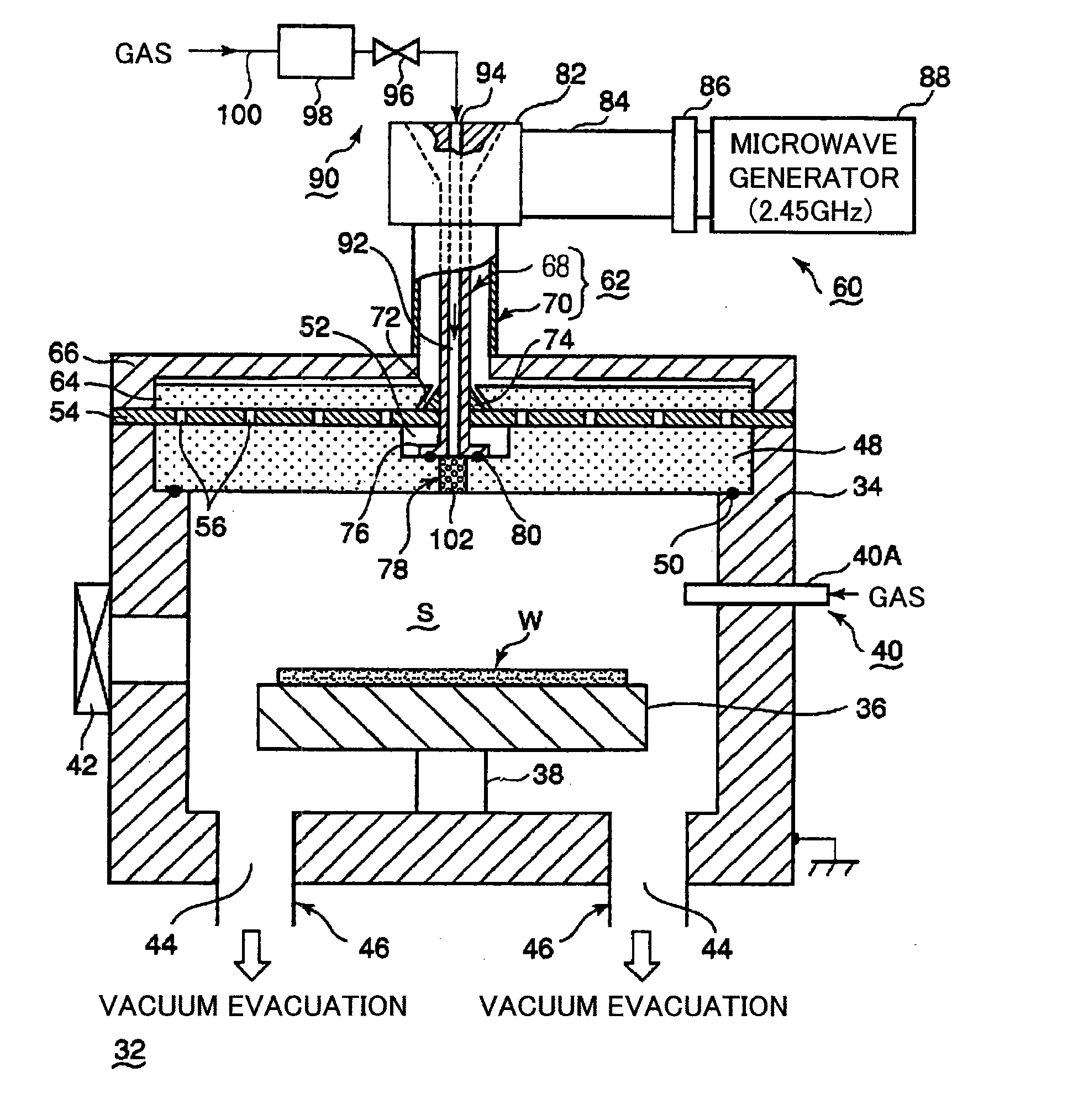
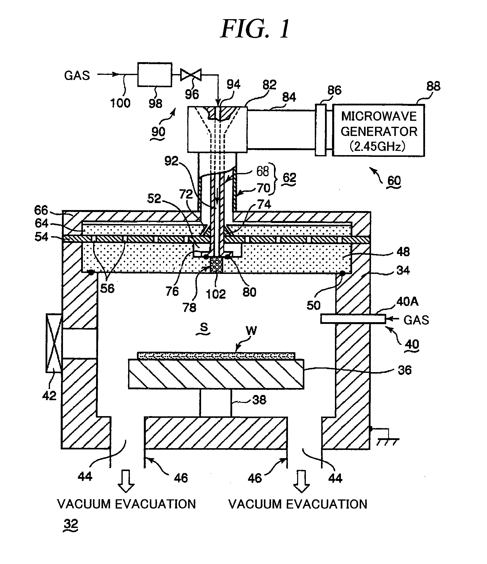
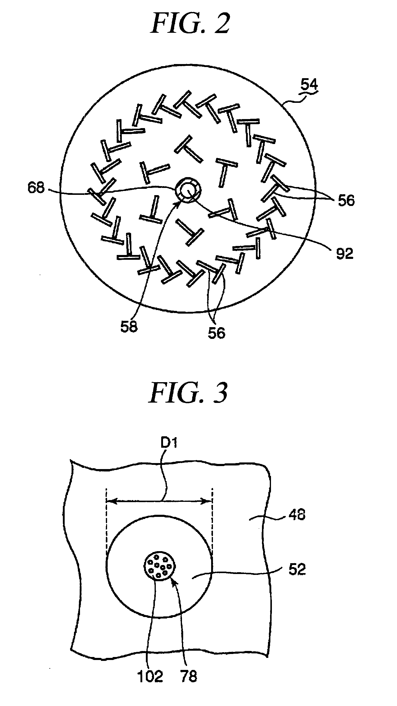
[0032]FIG. 1 is a configuration view illustrating a plasma processing apparatus in accordance with an embodiment of the present invention. FIG. 2 is a plan view illustrating a planar antenna member of the plasma processing apparatus illustrated in FIG. 1. FIG. 3 is a plan view illustrating an electric field attenuating recess of the plasma processing apparatus illustrated in FIG. 1. FIG. 4 is a partial enlarged cross-sectional view illustrating the electric field attenuating recess of the plasma processing apparatus shown in FIG. 1. FIG. 5 is an enlarged cross-sectional view illustrating a coaxial waveguide of the plasma processing apparatus in FIG. 1. FIG. 6 is a cross-sectional view taken along a line A-A of FIG. 5.

[0033]As shown in FIG. 1, a plasma processing apparatus (plasma etching apparatus) 32 in ...


PUM

PropertyMeasurementUnit
diameteraaaaaaaaaa
frequencyaaaaaaaaaa
pressureaaaaaaaaaa

Abstract

The present invention relates to a plasma processing apparatus including: a processing chamber whose ceiling portion is opened and the inside thereof can be evacuated to vacuum; a ceiling plate which is made of dielectric material and is airtightly mounted to an opening of the ceiling portion; a planar antenna member which is installed on a top surface of the ceiling plate, for introducing a microwave into the processing chamber; and a coaxial waveguide, which has a central conductor connected to the planar antenna member, for supplying the microwave, wherein a gas passage is formed to pass through the central conductor, the planar antenna member, and the ceiling plate, and an electric field attenuating recess for attenuating an electric field intensity of the center portion of the ceiling plate is installed on a top surface of a center area of the ceiling plate.

Description

TECHNICAL FIELD[0001]The present invention relates to a plasma processing apparatus used for processing a semiconductor wafer or the like by applying thereon plasma generated by a microwave.BACKGROUND ART[0002]Along with a recent trend of a high density and a high miniaturization of semiconductor devices, a plasma processing apparatus has been used for performing a film forming process, an etching process, an ashing process and the like in a manufacturing process of the semiconductor devices. Especially, since plasma can be stably generated even in an environment of a high vacuum level in which a pressure is comparatively low, e.g., from about 0.1 mTorr (13.3 mPa) to several tens mTorr (several Pa), a microwave plasma apparatus for generating high-density plasma by using a microwave tends to be used.[0003]Such a plasma processing apparatus is disclosed in Japanese Patent Laid-open Publication Nos. H3-191073, H5-343334, H9-181052, 2003-332326, or the like. Herein, a typical microwave...

Claims


Application Information

Patent Timeline
Patent Type & Authority Applications(United States)
IPC IPC(8): B44C1/22C23C16/00
CPCH01J37/32192H05H1/46H01J37/3244H01J37/3222C23C16/511H01L21/67207F04D17/168C23C16/4586H01L21/0262
Inventor TIAN, CAIZHONGNISHIZUKA, TETSUYANOZAWA, TOSHIHISA
Owner TOKYO ELECTRON LTD
Why Eureka
Try Eureka