Method for obtaining a scintillation structure

a scintillation structure and scintillation beam technology, applied in the field of scintillation beam structure obtaining method, can solve the problems of affecting the optimal machining of hygroscopic crystals, affecting the accuracy of gamma photon gamma radiation,

Active Publication Date: 2009-10-01
CONSIGLIO NAT DELLE RICERCHE
View PDF9 Cites 8 Cited by
  • Summary
  • Abstract
  • Description
  • Claims
  • Application Information

AI Technical Summary

Benefits of technology

[0023]An additional object of the present invention is to make available a method for obtaining a scintillation structure that assures a perfect mutual alignment of the scintillation crystals and a perfect orthogonality with respect to the photomultiplier.
[0025]A further object of the present invention is to make available a method for obtaining a scintillation structure that assures that each crystal cannot move with respect to the channels of a collimator.

Problems solved by technology

In general, this entails an erroneous calculation of the position of the interaction of the gamma photon.
Metals having high atomic number (and hence high density) are more difficult to traverse for gamma photons than epoxy resins.
However, because of obvious construction difficulties, the solution with a single collimation structure and integrated crystals does not allow an optimal machining of hygroscopic crystals which need to be completely isolated from the surrounding environment.
Moreover, the insertion of individual crystals into the collimation channels entails additional drawbacks linked to the need to anchor the individual crystals to prevent them from moving along the channels of the collimator.
Additionally, positioning each crystal in such a way that it is perfectly aligned to the channel in which it lies and that all the crystals are arranged with the respective walls oriented towards the photomultiplier to form a single plane, perfectly orthogonal to the channel of the collimator, is very difficult and it requires considerable resources.

Method used


Image

  • Method for obtaining a scintillation structure
  • Method for obtaining a scintillation structure
  • Method for obtaining a scintillation structure

Examples


Embodiment Construction

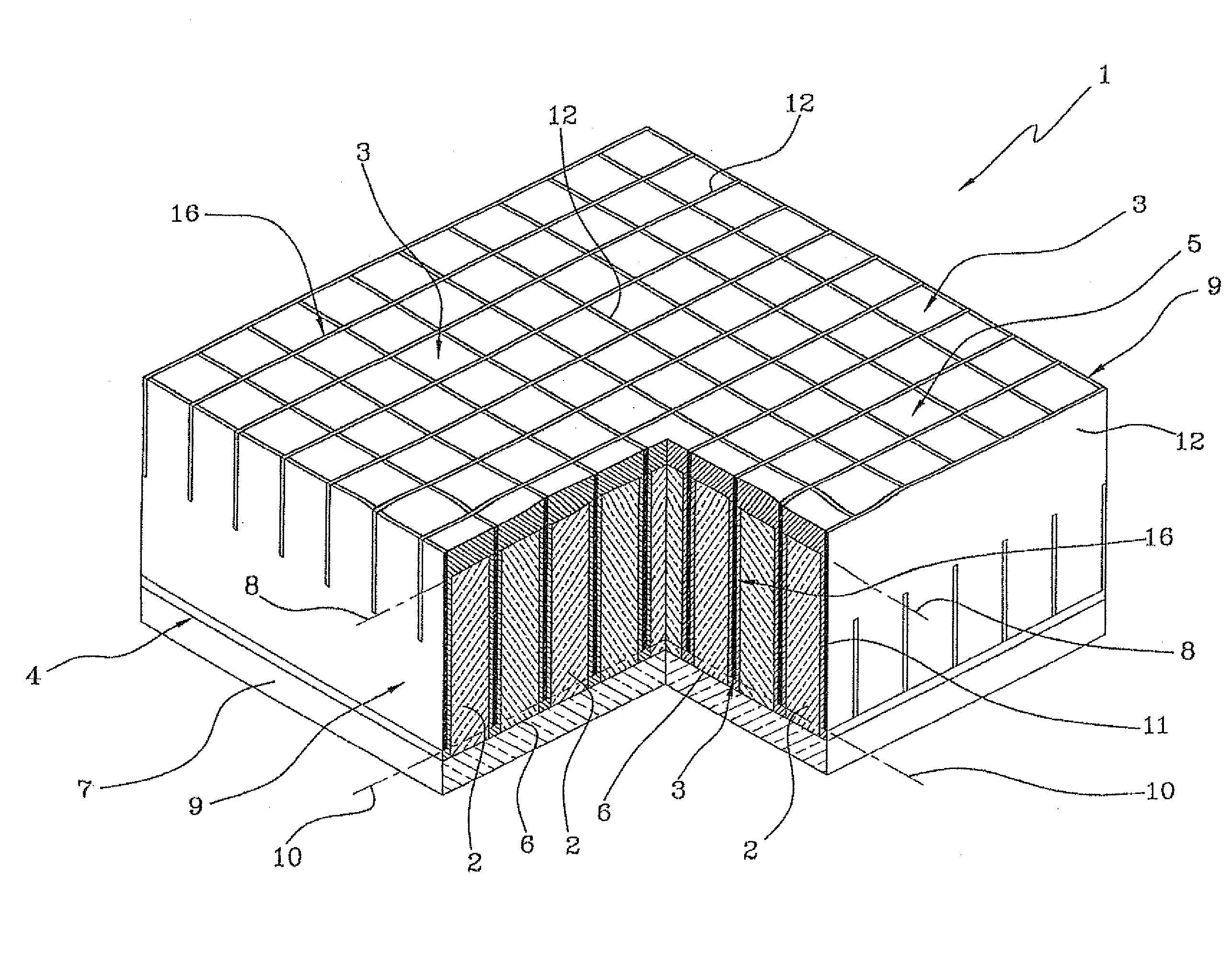
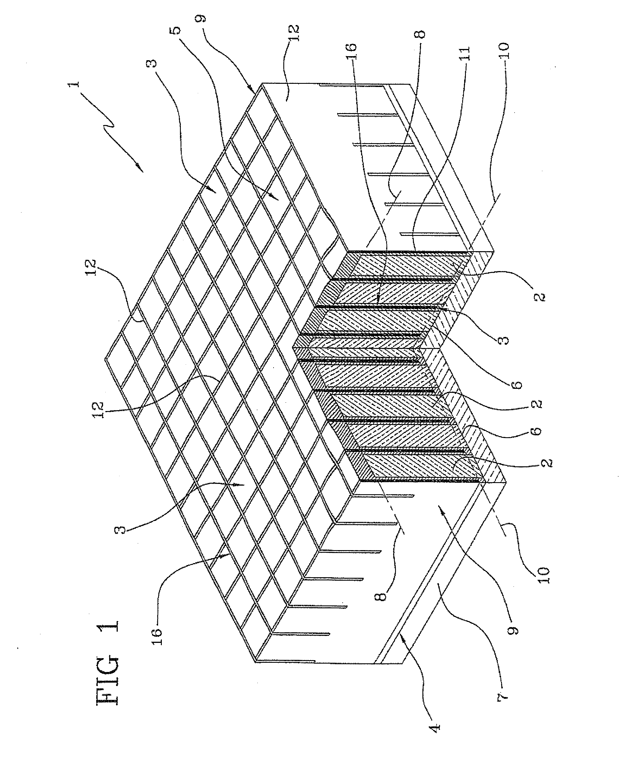
[0034]With reference to the accompanying figures, the reference number 1 designates in its entirety a scintillation structure according to the present invention.

[0035]The scintillation structure 1 is particularly suited to be used in a gamma chamber usable in different applications, such as Nuclear Medicine (SPECT and PET) in order to identify pathologies, perform the scintigraphic analysis of small animals to test radio-labeled new antibodies and peptides, astrophysics and industrial systems for non destructive tests.

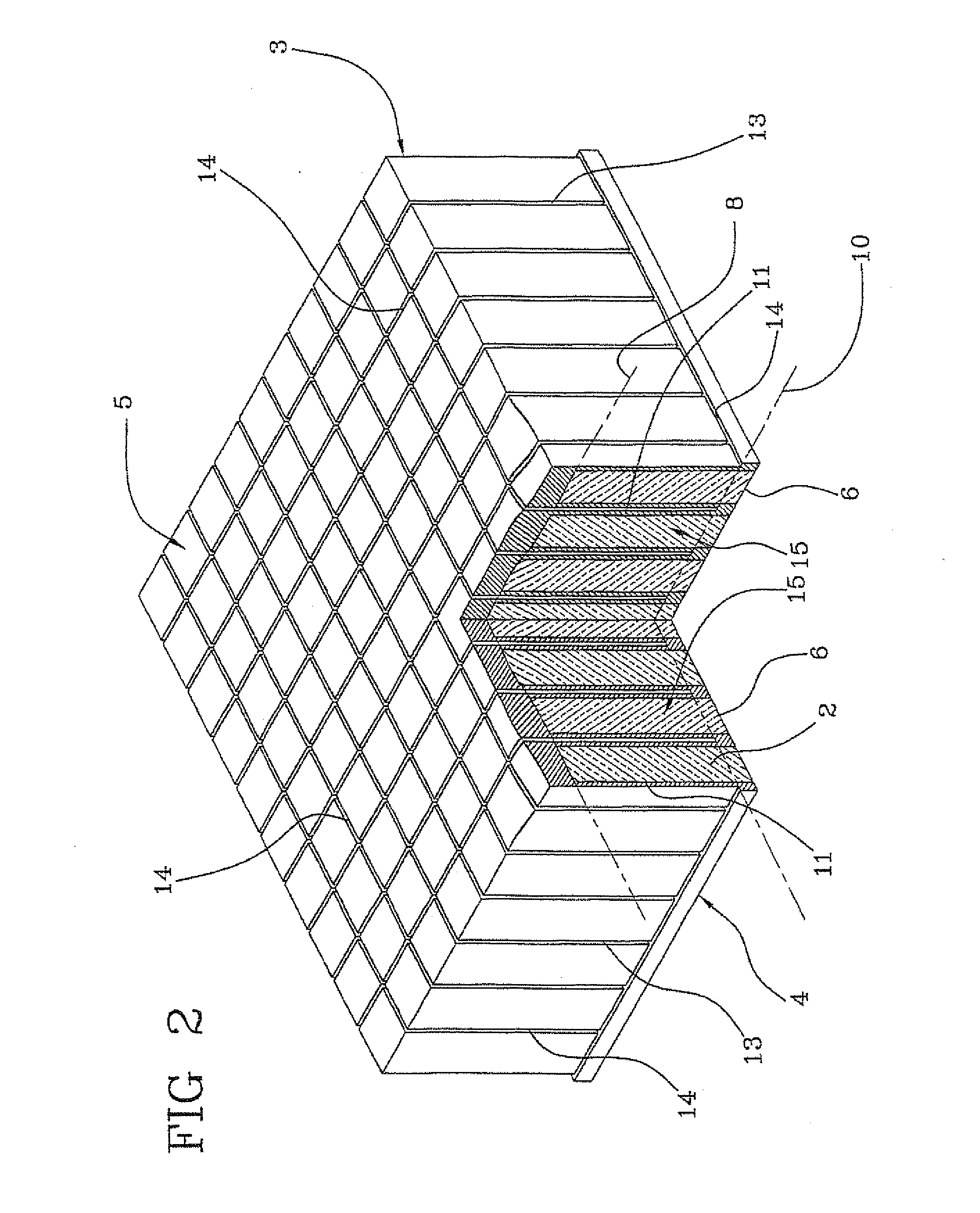
[0036]The scintillation structure 1 comprises a plurality of scintillation crystals 2. The scintillation crystals 2 in the preferred embodiment illustrated in the accompanying drawing are shaped as a right prism with square base, however they can have any other prismatic shape.

[0037]The scintillation crystals 2 can be inorganic or organic, hyper-pure, or doped to enhance their scintillation properties according to the type of application to be obtained, to the diagnost...


PUM


Abstract

A method for obtaining a scintillation body comprising the steps of readying a matrix of binding material within which is present a plurality of scintillation crystals, obtaining a plurality of channels within the matrix and around the crystals and inserting metallic material having a high atomic number and high density between mutually adjacent scintillation crystals without separating the scintillation crystals from the matrix of binding material.

Description

TECHNICAL FIELD [0001]The present invention relates to a method for obtaining a scintillation structure of the type used in gamma cameras.BACKGROUND OF INVENTION [0002]The gamma camera is substantially constituted by three fundamental elements: a collimator a scintillation structure and one or more photomultipliers.[0003]The collimator is placed between an object that emits gamma radiation and the scintillation structure and has the function of allowing the passage only of the radiation directed perpendicularly to the scintillation structure screening all radiation directed perpendicularly to the scintillation structure shielding all radiation directed in different directions.[0004]It should be noted that gamma radiation, composed of gamma photons, cannot be deviated by optical lenses (e.g. it takes place for the photons emitted in the visible range in traditional photography) because of their penetrating power and they also do not have electrical charge. The photon beam is then mod...

Claims


Application Information

Patent Timeline
IPC IPC(8): C09K11/02
CPCG01T1/1644
Inventor SOLURI, ALESSANDROMASSARI, ROBERTOTROTTA, CARLOSCOPINARO, FRANCESCO
Owner CONSIGLIO NAT DELLE RICERCHE
Why Eureka
Try Eureka