
Wire bonding on reactive metal surfaces of a metallization of a semiconductor device by providing a protective layer

a reactive metal surface and semiconductor technology, applied in the field of integrated circuits, can solve the problems of high non-reliable bond connection, difficult to achieve wire bonding on copper bond pads, and no longer restricted overall signal delay of devices, so as to reduce overall process complexity and production costs, and not negatively affect the bond process

Inactive Publication Date: 2009-10-01
GLOBALFOUNDRIES INC
View PDF4 Cites 27 Cited by
  • Summary
  • Abstract
  • Description
  • Claims
  • Application Information

AI Technical Summary

Benefits of technology

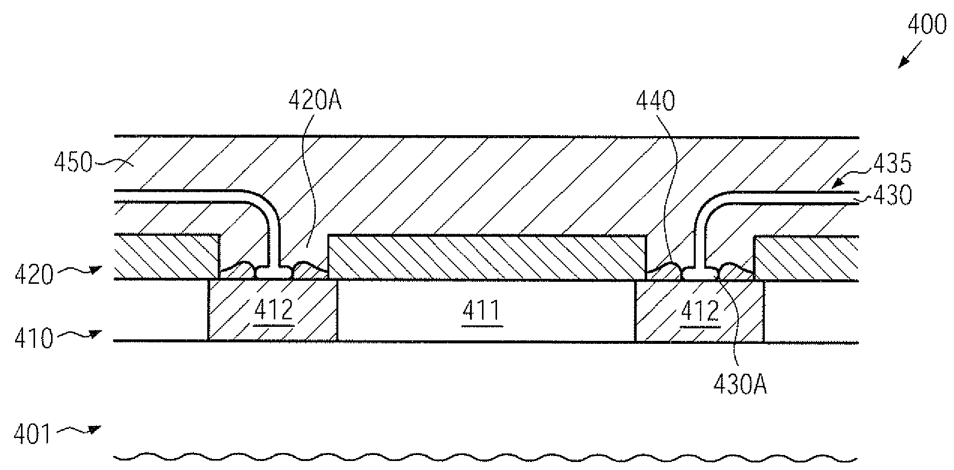
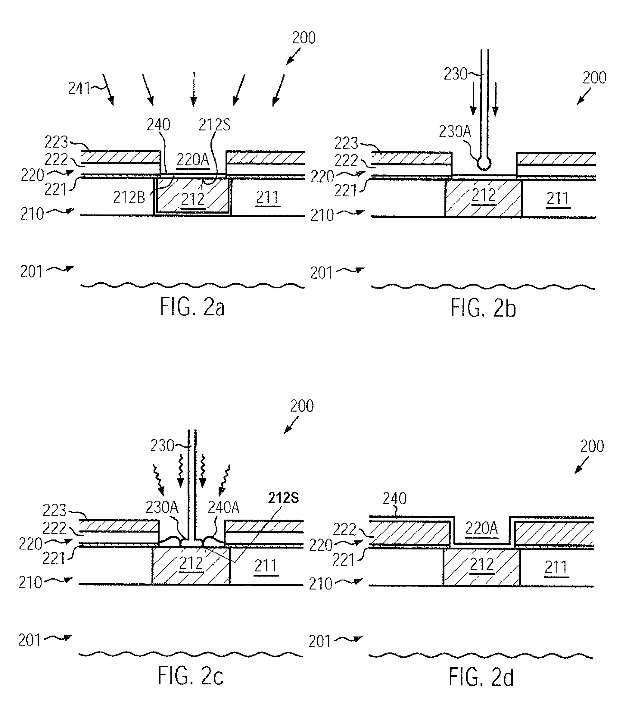
[0014]Generally, the subject matter disclosed herein relates to techniques and semiconductor devices in which wire bonding in copper-based metallization structures may be accomplished without using aluminum-based techniques by passivating an exposed copper-containing surface prior to and during the wire bonding process. For this purpose, an appropriate protective layer with a suitably adapted thickness may be formed after patterning the passivation layer stack, wherein the protective layer may be maintained during the wire bonding process, thereby providing uniform process conditions while not negatively affecting the bond process. That is, the protective layer may sufficiently passivate the reactive copper surface while also allowing the attaching of a bond wire “through” the protective layer, thereby obtaining a reliable intermetallic connection between the copper material and the bond wire, wherein, in some illustrative aspects disclosed herein, material of the protective layer may be provided as a type of material that may have to be used in previous manufacturing sequences, thereby substantially not contributing to increased requirements in terms of additional process tools. In some illustrative aspects, the processing of aluminum may be avoided during the formation of a copper-based metallization system and a corresponding wire bonding process, thereby significantly reducing overall process complexity and production costs compared to conventional approaches, as previously described.

Problems solved by technology

Over many decades, aluminum has been used as the metal of choice for forming the metal features in the metallization layers of the semiconductor devices, due to its moderately high thermal and electrical conductivity, its self-limiting creation of a passivating oxide layer and its compatibility with other materials and process techniques used for fabricating integrated devices.
With the continuous reduction of the circuit dimensions, the dimensions of the metal features have resulted in a situation in which the overall signal delay in the devices is no longer restricted by the performance of the individual semiconductor circuit elements, such as the switching speed of the transistors, but is substantially determined by the parasitic time constants in the metallization system caused by the restricted conductivity of aluminum and the parasitic capacitance between neighboring metal regions.
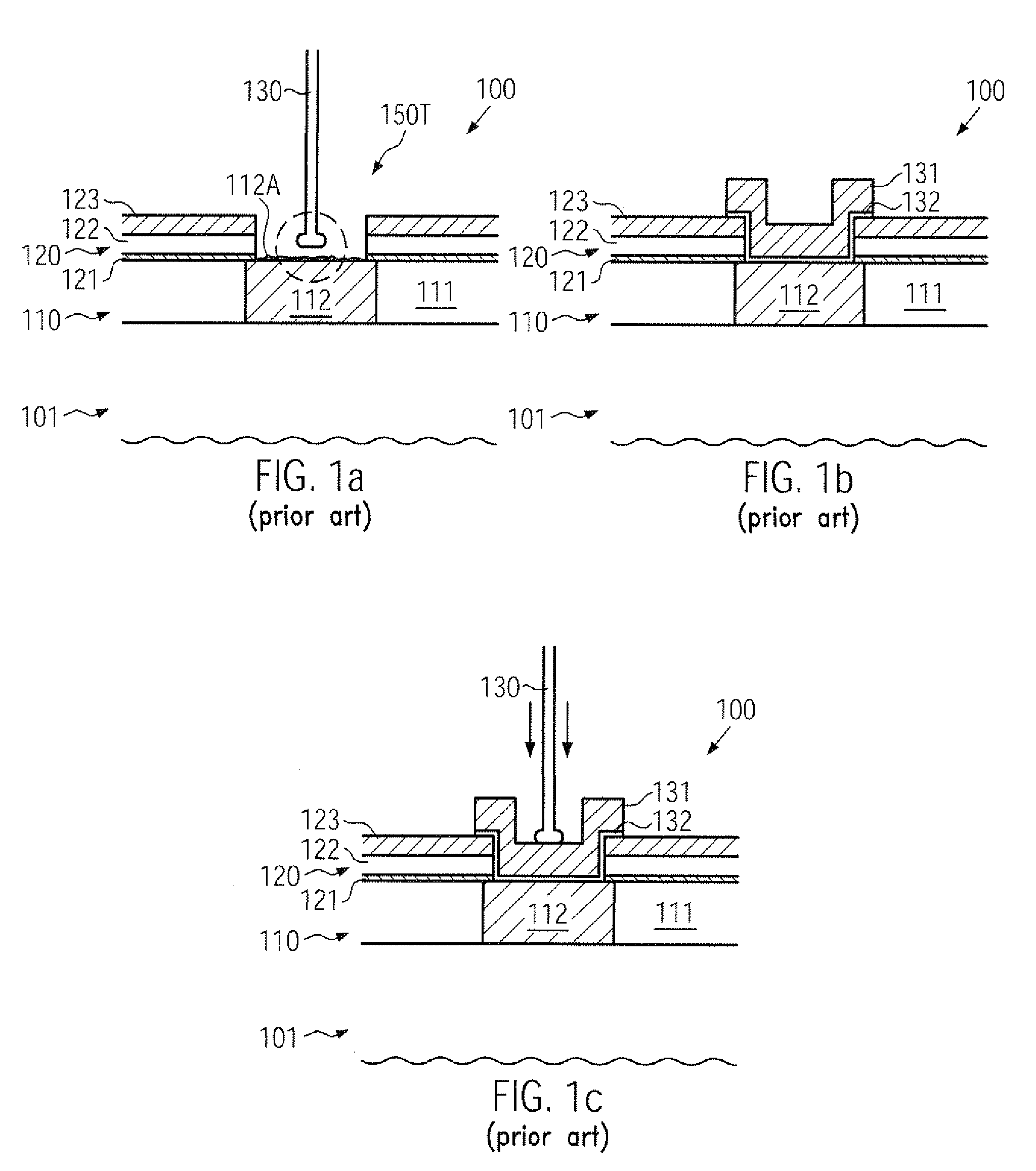
In a production environment, however, the wire bonding on copper bond pads is very difficult to achieve due to an inhomogeneous self-oxidization of the copper surface in combination with extensive corrosion, which may result in highly non-reliable bond connections.
For this reason, a different terminal metal, such as an aluminum metal layer, may be used in an advanced metallization structure based on copper, possibly in combination with low-k dielectrics, which may result in a more complex manufacturing process, since respective process tools and processes for forming and patterning aluminum layers have to be provided in the production line.
Consequently, in a complex manufacturing environment, respective resources for depositing and patterning the aluminum layer 131 in combination with the barrier / adhesion layer 132 may have to be provided in addition to equipment and materials required for the formation of a complex copper-based metallization system, thereby contributing to increased cycle times and thus production costs.

Method used


Image

  • Wire bonding on reactive metal surfaces of a metallization of a semiconductor device by providing a protective layer
  • Wire bonding on reactive metal surfaces of a metallization of a semiconductor device by providing a protective layer
  • Wire bonding on reactive metal surfaces of a metallization of a semiconductor device by providing a protective layer

Examples


Embodiment Construction

[0028]Various illustrative embodiments are described below. In the interest of clarity, not all features of an actual implementation are described in this specification. It will of course be appreciated that in the development of any such actual embodiment, numerous implementation-specific decisions must be made to achieve the developers' specific goals, such as compliance with system-related and business-related constraints, which will vary from one implementation to another. Moreover, it will be appreciated that such a development effort might be complex and time-consuming, but would nevertheless be a routine undertaking for those of ordinary skill in the art having the benefit of this disclosure.

[0029]The present subject matter will now be described with reference to the attached figures. Various structures, systems and devices are schematically depicted in the drawings for purposes of explanation only and so as to not obscure the present disclosure with details that are well kno...


PUM

PropertyMeasurementUnit
thicknessaaaaaaaaaa
gate lengthaaaaaaaaaa
dielectric constantaaaaaaaaaa

Abstract

In semiconductor devices having a copper-based metallization system, bond pads for wire bonding may be formed directly on copper surfaces, which may be covered by an appropriately designed protection layer to avoid unpredictable copper corrosion during the wire bond process. A thickness of the protection layer may be selected such that bonding through the layer may be accomplished, while also ensuring a desired high degree of integrity of the copper surface.

Description

BACKGROUND OF THE INVENTION[0001]1. Field of the Invention[0002]The present disclosure generally relates to the field of integrated circuits, and, more particularly, to a back end of line processing for a wire bonding structure in sophisticated metallization structures, including highly reactive metals, such as copper and the like.[0003]2. Description of the Related Art[0004]The manufacturing of integrated circuits involves many complex process steps to form circuit elements, such as transistors, capacitors, resistors and the like, in and above an appropriate semiconductor material. In recent years, enormous advances have been made in increasing integration density and overall functionality of the integrated circuits. These advances have been achieved by scaling the individual circuit elements to dimensions in the deep sub-micrometer range, with currently used critical dimensions, such as the gate length of a field effect transistor, of 30 nm and less. Hence, millions of circuit ele...

Claims


Application Information

Patent Timeline
Patent Type & Authority Applications(United States)
IPC IPC(8): H01L23/522H01L21/768H01L21/311H01R43/02
CPCH01L24/05H01L24/45H01L24/48H01L24/85H01L2224/04042H01L2224/05082H01L2224/05147H01L2224/05166H01L2224/05181H01L2224/05187H01L2224/05624H01L2224/05647H01L2224/45124H01L2224/45144H01L2224/45147H01L2224/48095H01L2224/48463H01L2224/48505H01L2224/48647H01L2224/48747H01L2224/85011H01L2224/85205H01L2224/85375H01L2924/01005H01L2924/01006H01L2924/01007H01L2924/01013H01L2924/01014H01L2924/01015H01L2924/01022H01L2924/01027H01L2924/01028H01L2924/01029H01L2924/01032H01L2924/01042H01L2924/01046H01L2924/01047H01L2924/01073H01L2924/01074H01L2924/01078H01L2924/01079H01L2924/01082H01L2924/01327H01L2924/014H01L2924/04941H01L2924/04953H01L2924/05042H01L2924/14H01L2924/19041H01L2924/19042H01L2924/19043H01L2924/30105H01L2924/01019H01L2924/01033H01L2924/01068H01L2924/01072H01L2224/48624H01L2224/48847H01L2224/48724H01L2224/02166H01L2924/1306Y10T29/4921H01L2924/00014H01L2224/05664H01L2924/00H01L2224/48824H01L2224/03009H01L2924/00015
Inventor LEHR, MATTHIASKUECHENMEISTER, FRANK
Owner GLOBALFOUNDRIES INC
Features
  • Generate Ideas
  • Intellectual Property
  • Life Sciences
  • Materials
  • Tech Scout
  • Unparalleled Data Quality
  • Higher Quality Content
  • 60% Fewer Hallucinations
Learn More