METHOD FOR PRODUCING SINTERED NdFeB MAGNET

a technology of ndfeb magnet and ndfeb, which is applied in the direction of magnetic materials, magnetic bodies, coatings, etc., can solve the problems of increasing the price of the magnet, and difficult to industrially use sintered ndfeb magnets produced by this method, etc., to achieve sufficient anticorrosion effect, increase the coercivity, and improve the effect of magnetic characteristics

Active Publication Date: 2009-10-08
DAIDO STEEL CO LTD
View PDF8 Cites 27 Cited by
  • Summary
  • Abstract
  • Description
  • Claims
  • Application Information

AI Technical Summary

Benefits of technology

[0028]To solve problems (2), (3) and (4), it is necessary to eliminate the needs for removing the surface layer, re-performing the machining or carrying out a chemical process such as pickling after the sintered NdFeB magnet is precisely machined and subjected to a grain boundary diffusion process to increase its coercivity. In other words, if the sintered NdFeB magnet can be used in practical applications immediately after the grain boundary diffusion process, the additional costs that the conventional methods require after the grain boundary diffusion process will be unnecessary, and the deterioration in the magnetic characteristics due to the machining or pickling will additionally be avoided. If the anticorrosion treatment after the machining becomes unnecessary

Problems solved by technology

However, Dy and Tb are scarce resources and unevenly distributed.
However, using a large amount of Ni and Co increases t

Method used


Image

  • METHOD FOR PRODUCING SINTERED NdFeB MAGNET
  • METHOD FOR PRODUCING SINTERED NdFeB MAGNET
  • METHOD FOR PRODUCING SINTERED NdFeB MAGNET

Examples


first example

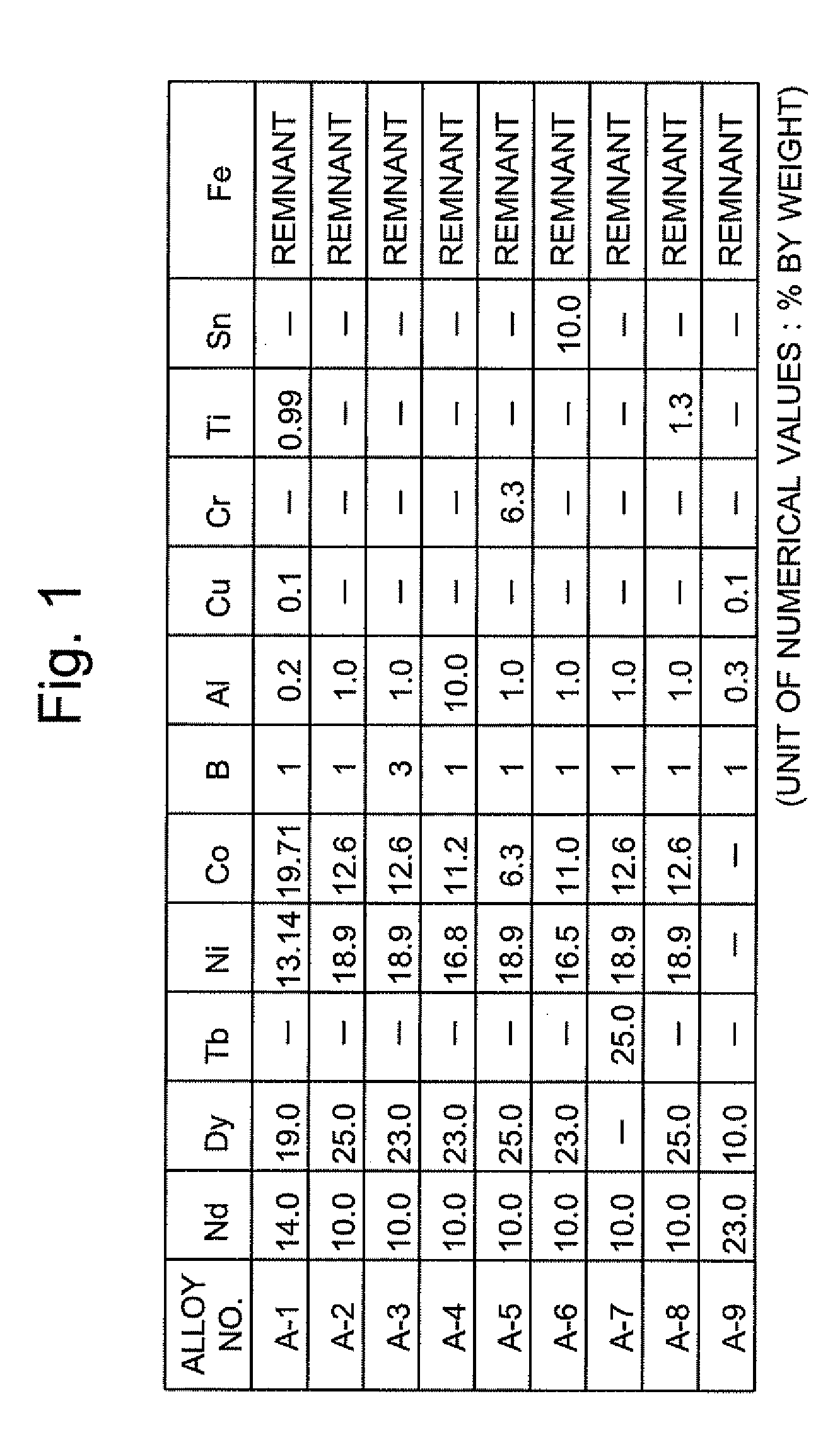
[0085]Eleven kinds of alloys shown in the table of FIG. 1, each containing Dy or Tb, were prepared by a strip-cast method. Each alloy was then subjected to hydrogen pulverization and jet-milling to obtain fine powders with average grain sizes of approximately 5 μm, 3 μm, 2 μm and 1.5 μm. The grain size was measured with a laser-type grain-size distribution measurement apparatus produced by Sympatec GmbH. The central value D50 of the grain size distribution was selected as the average grain size.

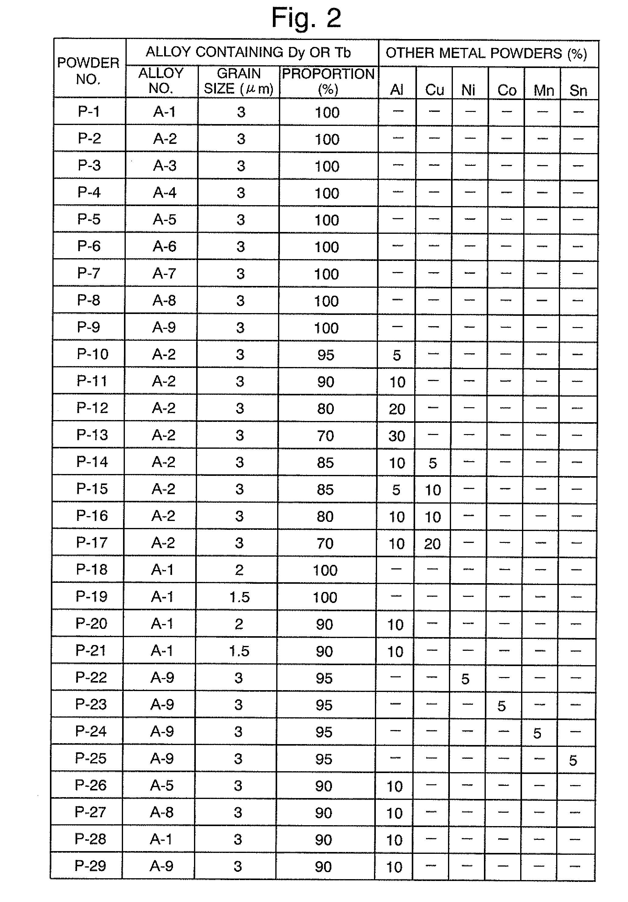
[0086]In addition to the fine powders of the alloys shown in the table of FIG. 1, fine powders prepared by mixing fine powders of Al, Cu, Ni, Co, Mn, Sn, Ag, Mo and W into the aforementioned powders were also used as the metal powders. The formulations and average grain sizes of these fine powders used in the experiment are shown in the table of FIG. 2.

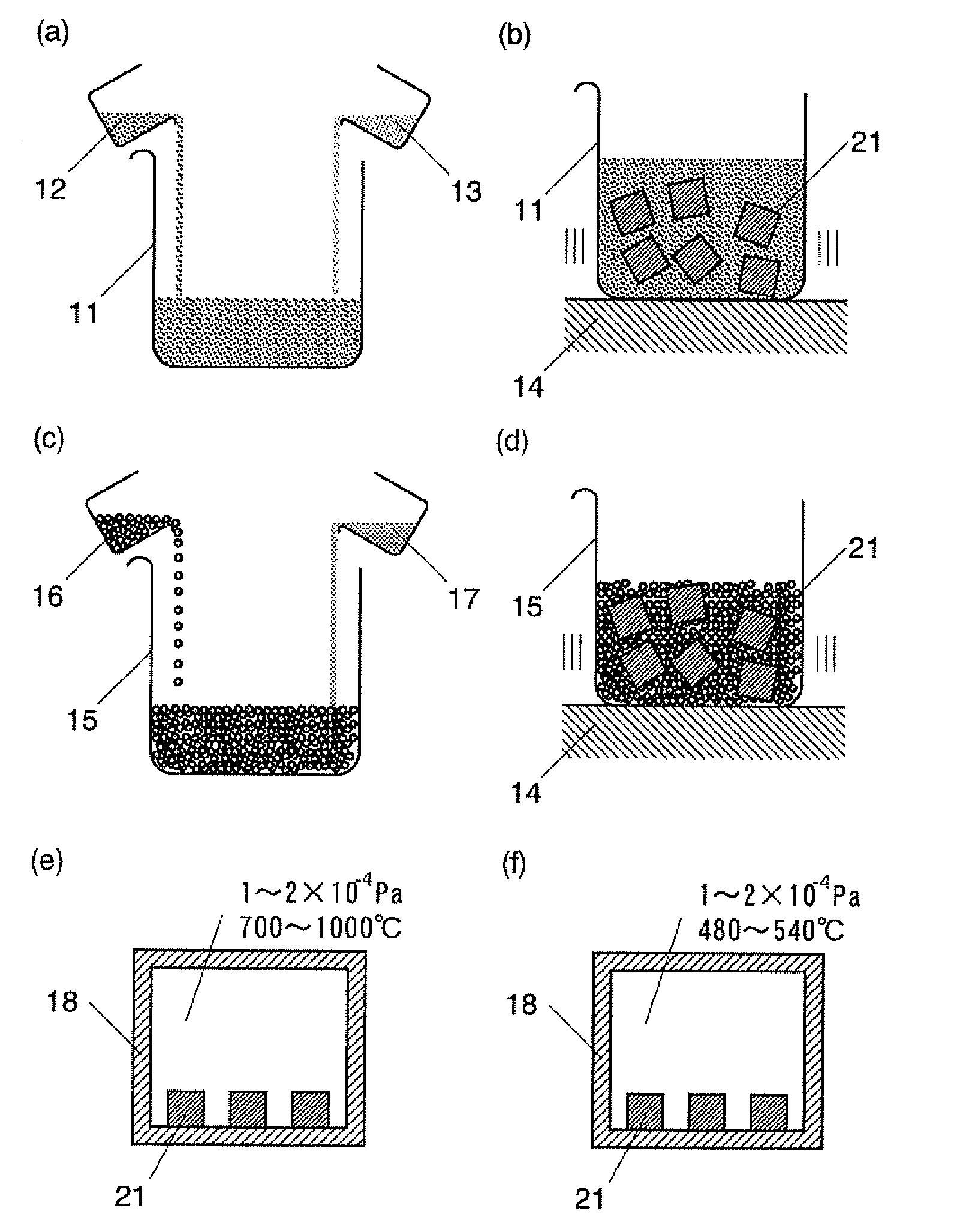
[0087]The formation of a metal powdered layer containing Dy or Tb on the surface of the sintered NdFeB magnet and the grain boundary diffusion...

second example

[0104]A strip-cast alloy having the composition M-1 was ground by the same method as in the first example to obtain a powder with D50=5 μm. Similar to the first example, the fine-grinding process was performed under different conditions, i.e. by mixing 100 to 3000 ppm of oxygen into nitrogen in the jet-milling process in one case or using pure nitrogen in another case, to obtain three kinds of fine powders differing in oxygen content. These powders were molded by a transverse magnetic-field molding method and sintered at a temperature of 980° to 1050° C. to obtain sintered compacts. These sintered compacts are hereinafter referred to as R-7, R-8 and R-9. R-7 to R-9 were subject to the heat treatment as in the first example, and three rectangular solid samples measuring 7 mm×7 mm×4 mm (the direction of 4 mm coinciding with the magnetization direction) were prepared for each of the sintered compacts. The average values of the oxygen contents of R-7 to R-9 are shown in FIG. 12. A grain...


PUM

PropertyMeasurementUnit
Grain sizeaaaaaaaaaa
Fractionaaaaaaaaaa
Fractionaaaaaaaaaa

Abstract

The present invention provides a method for producing a sintered NdFeB magnet having high coercivity and capable of being brought into applications without lowering its residual magnetic flux density or maximum energy product and without reprocessing. The method for producing a sintered NdFeB magnet according to the present invention includes applying a substance containing dysprosium (Dy) and/or terbium (Tb) to the surface of the sintered NdFeB magnet forming a base body and then heating the magnet to diffuse Dy and/or Tb through the grain boundary and thereby increase the coercivity of the magnet. This method is characterized in that: (1) the substance containing Dy or Tb to be applied to the surface of the sintered NdFeB magnet is substantially a metal powder; (2) the metal powder is composed of a rare-earth element R and an iron-group transition element T, or composed of R, T and another element X, the element X capable of forming an alloy or intermetallic compound with R and/or T; and (3) the oxygen content of the sintered NdFeB magnet forming the base body is 5000 ppm or lower. The element T may contain nickel (Ni) or cobalt (Co) to produce an anticorrosion effect.

Description

TECHNICAL FIELD[0001]The present invention relates to a method for producing a rare-earth magnet, and particularly to a method for producing a sintered NdFeB magnet with increased coercivity.BACKGROUND ART[0002]Sintered NdFeB magnets are expected to be in greater demand in the future as a component of the motor of a hybrid car or other devices. Accordingly, a further increase in its coercivity has been demanded. One well-known method for increasing the coercivity HcJ of the sintered NdFeB magnet is to substitute dysprosium (Dy) or terbium (Tb) for a portion of neodymium (Nd). However, Dy and Tb are scarce resources and unevenly distributed. Furthermore, the substitution by these elements decreases the residual magnetic flux density Br and the maximum energy product (BH)max of the sintered NdFeB magnet.[0003]It has recently been found that the HcJ can be increased with almost no decrease in the Br of the magnet by applying Dy or Tb to the surface of the sintered NdFeB magnet by sputt...

Claims


Application Information

Patent Timeline
IPC IPC(8): B05D3/02B05D5/00B05D7/00
CPCB22F3/1039H01F41/0293B22F2003/248B22F2999/00C22C38/005C22C38/06C22C38/08C22C38/10H01F1/0577B22F7/06H01F41/005B22F2202/01B22F2201/20H01F41/02B22F1/00B22F3/24
Inventor SAGAWA, MASATO
Owner DAIDO STEEL CO LTD
Why Eureka
Try Eureka