Method and apparatus for anode oxidation prevention and cooling of a solid-oxide fuel cell stack

Inactive Publication Date: 2009-10-08
DELPHI TECH INC
View PDF8 Cites 20 Cited by
  • Summary
  • Abstract
  • Description
  • Claims
  • Application Information

AI Technical Summary

Benefits of technology

[0011]Briefly described, an apparatus and method for a normal system shutdown of a SOFC system implements a control strategy that utilizes component hardware already available for normal operation of the SOFC system. This unique and novel control strategy enables the SOFC system to generate the fluid needed for prevention of oxidation during the cooling process of the anode side of the SOFC stack by converting the conventional system fuel supply for the delivery of a reducing fluid to the anode side of the SOFC stack during normal system shutdown. Purging the anode side of the SOFC stack is accomplished with a reducing fluid that is generated by using existing system hardware and the conventional fuel supply. As a result, the anode side of the stack is protected from oxidation and the cyclic stress that such oxidation would subject the hardware to is prevented, thereby prolonging the life of the SOFC system.
[0012]An additional benefit of the invention lies in the system's ability to control the temperature gradient that exists across the system hardware. The undesirable thermal stress that is c

Problems solved by technology

Due to the relative high operating temperature of the SOFC stack, typically about 750° C. and higher, and the chemical composition of the anodes, which are the system's functional and most vulnerable components, purging the entire SOFC stack with cathode air for cooling results in a degrading and fatiguing oxidation of the anodes.
At temperatures above about 400° C., and in the presence of free oxygen, nickel oxide is formed, which may lead to deterioration of the SOFC stack ove

Method used


Image

  • Method and apparatus for anode oxidation prevention and cooling of a solid-oxide fuel cell stack
  • Method and apparatus for anode oxidation prevention and cooling of a solid-oxide fuel cell stack
  • Method and apparatus for anode oxidation prevention and cooling of a solid-oxide fuel cell stack

Examples


Embodiment Construction

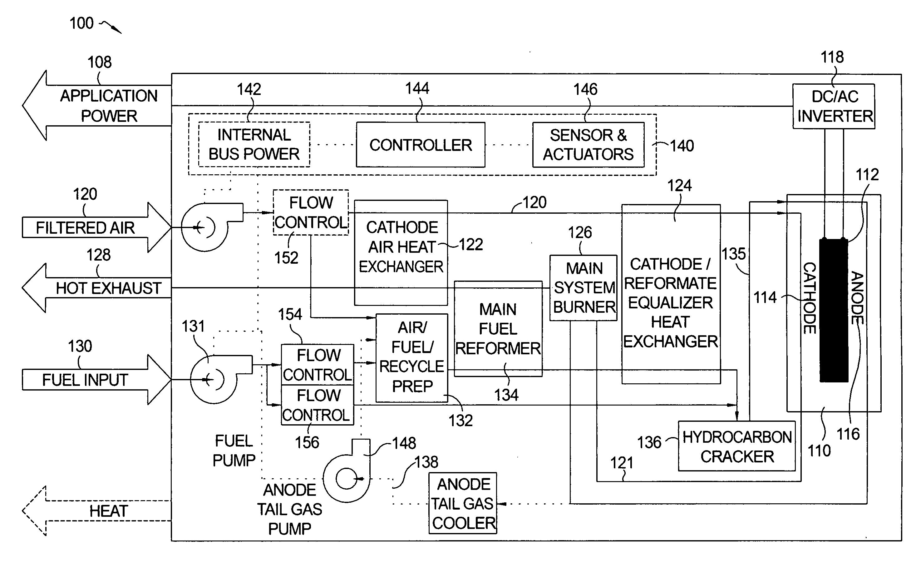
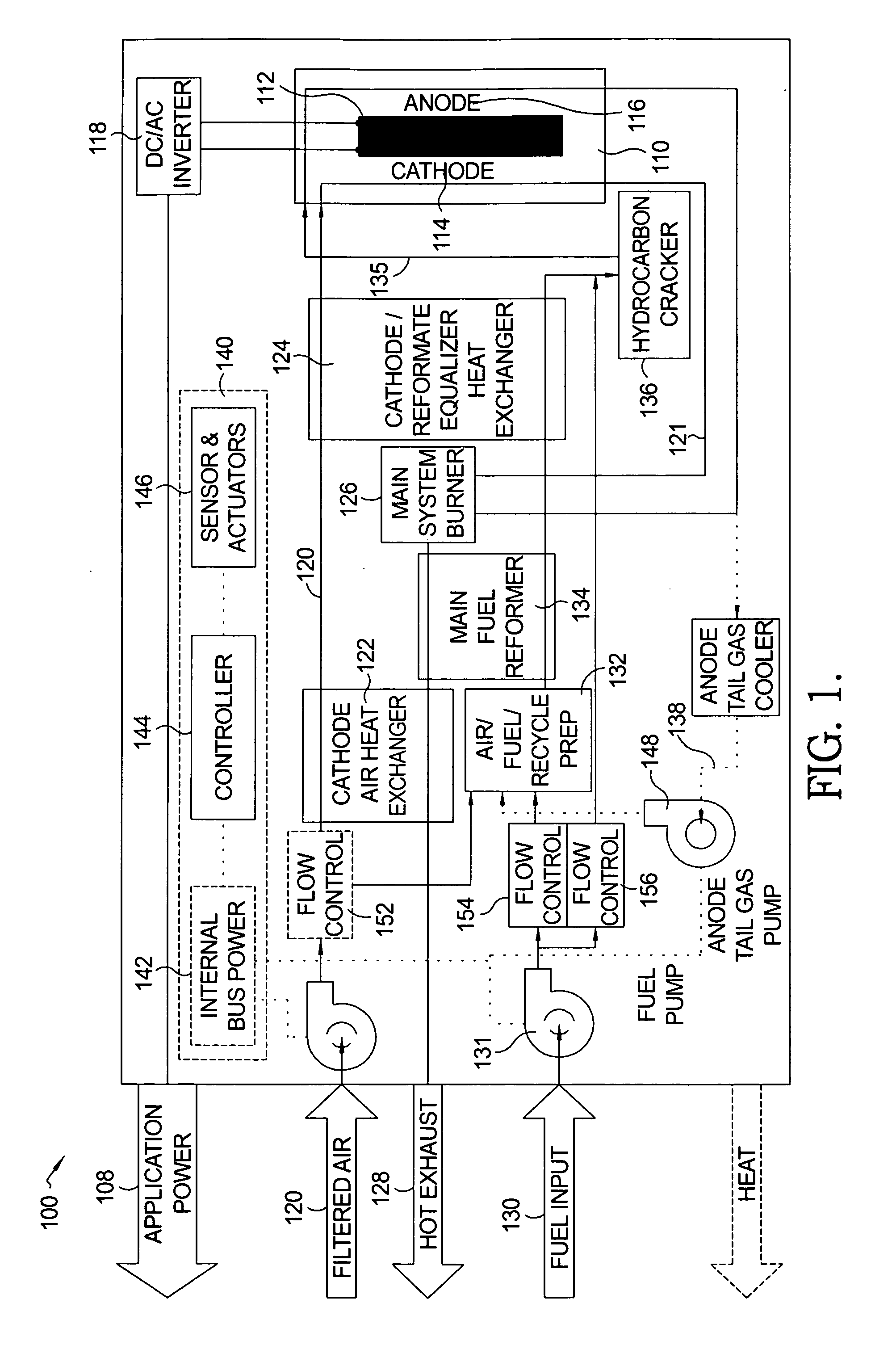
[0018]Referring to FIG. 1, a schematic mechanization diagram of an SOFC system 100 in accordance with the invention is illustrated. The SOFC system 100 includes at least one SOFC stack 110 as well as auxiliary equipment and controls. SOFC stack 110 includes a plurality of solid-oxide fuel cells 112 stacked together in electrical series. Each of the fuel cells 112 includes a cathode 114 and an anode 116, the plurality of cathodes 114 forming the cathode side of stack 110 and the plurality of anodes 116 forming the anode side of stack 110. Because each anode 116 and cathode 114 must have a free space for fluid passage over its surface, the cathode side and the anode side of stack 110 are typically separated by perimeter spacers which are selectively vented to permit fluid flow to the anodes 116 and cathodes 114 as desired but which also form seals on the axial surfaces to prevent fluid leakage from the cathode side of stack 110 to the anode side of stack 110 and vise versa. Thus, all ...


PUM


Abstract

An apparatus and method for a normal system shutdown of a SOFC system implements a control strategy that utilizes existing system hardware and operating processes already used during normal operation of the SOFC system. The control strategy enables the SOFC system to generate the fluid needed for prevention of oxidation during the cooling process of the anode side of the SOFC stack by converting the conventional system fuel supply for delivery of a reducing fluid to the anode side of the SOFC stack during normal system shutdown thereby preventing subjecting the hardware to cyclic stress that typically occurs during oxidation. The control strategy further enables the SOFC system to control the temperature gradient that exists across the system hardware thereby eliminating induction of thermal stress on the hardware, hence prolonging the life of the system hardware.

Description

GOVERNMENT INTEREST[0001]The present invention was supported in part by a U.S. Government Contract, No. DE-FC2602NT41246. The United States Government may have rights in the present invention.TECHNICAL FIELD[0002]The present invention relates to hydrogen / oxygen fuel cells having a solid-oxide electrolyte layer separating an anode layer from a cathode layer; more particularly, to fuel cell assemblies and systems including a plurality of individual fuel cells in a stack wherein air and reformed fuel are supplied to the stack; and most particularly, to an apparatus and method for anode oxidation prevention within the stack during normal system shutdown and a stack cooling strategy.BACKGROUND OF THE INVENTION[0003]Fuel cells, which generate electric current by the electrochemical combination of hydrogen and oxygen, are well known. In one form of such a fuel cell, an anodic layer and a cathodic layer are separated by an electrolyte formed of a ceramic solid oxide. Such a fuel cell is kno...

Claims


Application Information

Patent Timeline
IPC IPC(8): H01M8/04H01M8/10H01M8/06
CPCH01M8/04014H01M8/04097H01M8/04201H01M8/04231H01M8/04343H01M8/04708Y02E60/525H01M8/04776H01M8/0612H01M8/0662H01M2008/1293Y02E60/50H01M8/04731
Inventor MERGLER, CHRISTOPHER M.
Owner DELPHI TECH INC
Why Eureka
Try Eureka