
Bone conducting floating mass transducers

a floating mass transducer and conducting technology, applied in the field of devices and methods for assisting hearing in persons, can solve problems such as the possibility of something going wrong, the inability of conventional acoustic hearing devices to be helpful to many hearing impaired, and the lack of sound insulation

Inactive Publication Date: 2009-10-08
VIBRANT MED EL HEARING TECH
View PDF5 Cites 78 Cited by
  • Summary
  • Abstract
  • Description
  • Claims
  • Application Information

AI Technical Summary

Benefits of technology

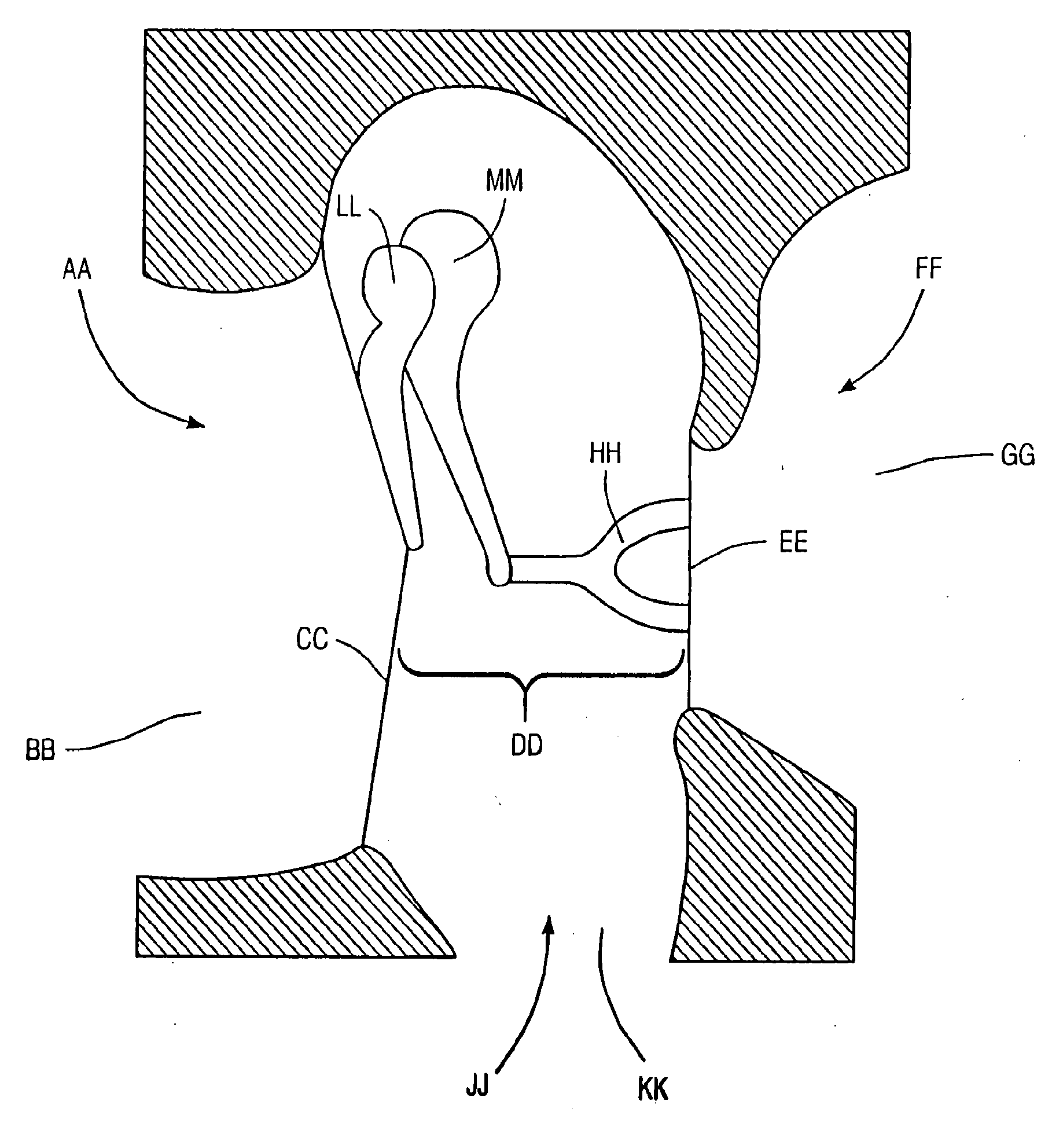
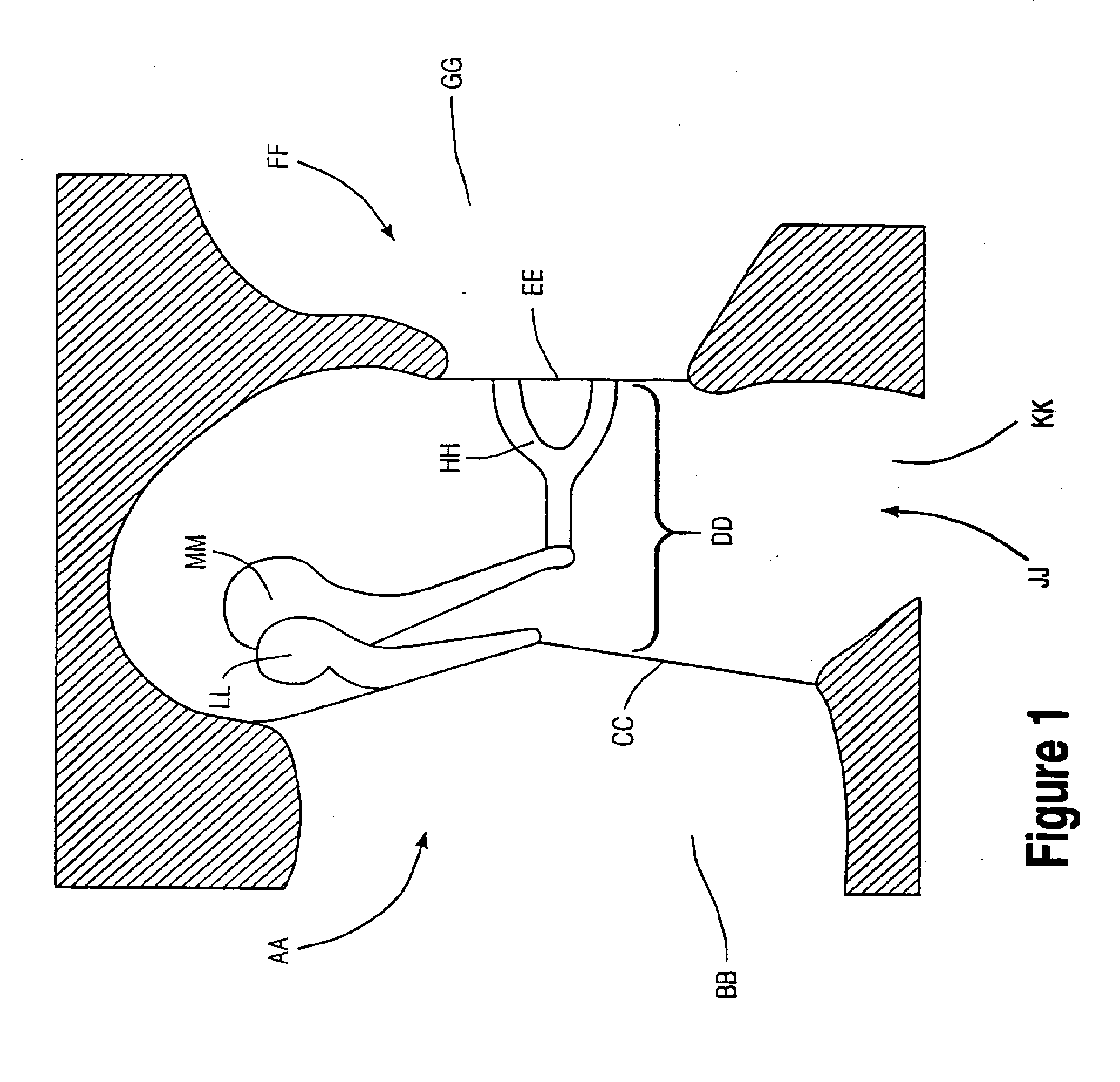
[0022]In another embodiment, the floating mass transducer includes a magnet secured within the housing. A coil is also disposed within the housing but, unlike the magnet, the coil is free to move within the housing. The housing includes a flexible diaphragm or other material to which the coil is attached. When an alternating current is provided to the coil, the coil generates a magnetic field that interacts with the magnetic field of the magnet, causing the magnet/housing and coil/diaphragm to vibrate relative to each other. The vibration of the diaphragm is translated into vibrations of the vibratory structure of the ear.
[0023]In still another embodiment, the floating mass transducer includes a bimorph piezoelectric strip disposed within the housing. The piezoelectric strip is secured at one

Problems solved by technology

As the human hearing system encompasses a complicated mix of acoustic, mechanical and neurological systems, there is ample opportunity for something to go wrong.
Unfortunately this is often the case.
Unfortunately for the hearing impaired, success in many professional and social situations may be becoming more dependent on effective hearing.
Although no one can argue that conventional acoustic hearing devices have not been helpful to many of the hearing impaired, the majority of the world wide impaired population, for whatever reason, has rejected their use.
A number of auditory system defects are known to impair or prevent hearing.
However, hearing loss in a person may be evidenced by one or more vibratory structures vibrating less than normal or not at all.
Moreover, the amplified sound produced by conventional hearing aids normally includes a significant amount of distortion.
Existing electromagnetic transducers present several problems.
Many are installed using complex surgical procedures which present the usual risks associated with major surgery and which also require disarticulating (disconnecting) one or more of the bones of the middle ear.
Disarticulation deprives the patient of any residual hearing he or she may have had prior to surgery, placing the patient in a worsened position if the implanted device is later found to be ineffective in improving the patient's hearing.
Existing devices also are incapable of producing vibrations in the middle ear which are substantially linear in relation to the current being conducted to the coil.
Thus, the sound produced by these devices includes significant distortion because the vibrations conducted to the inner ear do not precisely correspond to the sound waves detected by the microphone.

Method used


Image

  • Bone conducting floating mass transducers
  • Bone conducting floating mass transducers
  • Bone conducting floating mass transducers

Examples


example 1

Transducer 4b

[0215]Transducer Construction: A 4.5 mm diameter by 2.5 mm length transducer, illustrated in FIG. 29, used a 2.5 mm diameter NdFeB magnet. A mylar membrane was glued to a 2 mm length by 3 mm diameter plastic drinking straw so that the magnet was inside the straw. The tension of the membrane was tested for what was expected to be the required tension in the system by palpating the structure with a toothpick. A 5 mm biopsy punch was used to punch holes into an adhesive backed piece of paper. One of the resulting paper backed adhesive disks was placed, adhesive side down, on each end of the assembly making sure the assembly was centered on the adhesive paper structure. A camel hair brush was used to carefully apply white acrylic paint to the entire outside surface of the bobbin-shaped structure. The painted bobbin was allowed to dry between multiple coats. This process strengthened the structure. Once the structure was completely dry, the bobbin was then carefully wrapped...

example 2

Transducer 5

[0218]Transducer Construction: A 3 mm length transducer (similar to Transducer 4b, FIG. 31) used a 2 mm diameter by 1 mm length NdFeB magnet. A mylar membrane was glued to a 1.8 mm length by 2.5 mm diameter plastic drinking straw so that the magnet was inside the straw. The remaining description of Transducer 5's construction is analogous to that of Transducer 4b in Example 1, supra, except that: i) a 3 mm biopsy punch was used instead of a 5 mm biopsy punch; and ii) a 48 gauge, 3 litz wire was used to wrap the bobbin structure instead of a 44 gauge wire.

[0219]Methodology: The transducer was glued to the long process of the incus with cyanoacrylate glue. The transducer was connected to the Crown amplifier which was driven by the computer pure-tone output. The current was recorded across a 10 ohm resistor in series with Transducer 5. The current to the transducer was set at 3.3 mA, 4 mA, 11 mA, and 20 mA and the measured voltage across the transducer was 1.2 V, 1.3 V, 2.2...

example 3

Transducer 6

[0221]Transducer Construction: A 4 mm diameter by 1.6 mm length transducer used a 2 mm diameter by 1 mm length NdFeB magnet. A soft silicon gel material (instead of the mylar membrane used in Examples 1 and 2) held the magnet in position. The magnet was placed inside a 1.4 mm length by 2.5 mm diameter plastic drinking straw so that the magnet was inside the straw and the silicon gel material was gingerly applied to hold the magnet. The tension of the silicon gel was tested for what was expected to be the required tension in the system by palpating the structure with a toothpick. The remaining description of Transducer 6's construction is analogous to that of Transducer 4b in Example 1, supra, except that: 1) a 4 mm biopsy punch was used instead of a 5 mm biopsy punch; and ii) a 48 gauge, 3 litz wire was used to wrap the bobbin structure instead of a 44 gauge wire.

[0222]Methodology: The transducer was placed between the incus and the malleus and moved into a “snug fit” po...


PUM


Abstract

A floating mass transducer for assisting hearing in a person is provided. Inertial vibration in the floating mass transducer (100) produces vibrations in the inner ear. In an exemplary embodiment, the floating mass transducer comprises a magnet assembly (12) and a coil (14) secured inside a housing (10) which is attached to bone within the middle ear. The coil is more rigidly secured to the housing than the magnet. The magnet assembly and coil are configured such that conducting alternating electrical current through the coil results in vibration of the magnet assembly and coil relative to one another. The vibration is caused by the interaction of the magnetic fields of the magnet assembly and coil. Because the coil is more rigidly secured to the housing than the magnet assembly, the vibrations of the coil cause the housing to vibrate. The floating mass transducer may generate vibrations in the inner ear by being attached to the skull or through a mouthpiece.

Description

[0001]This application is a Continuation Application of, and claims the benefit of application Ser. No. 08 / 568,006, filed Dec. 6, 1995 which is a Continuation-In-Part Application of application Ser. No. 08 / 368,219 filed Jan. 3, 1995, which is a Continuation-In-Part of application Ser. No. 08 / 225,153 filed on Apr. 8, 1994, which is a Continuation-In-Part Application of application Ser. No. 08 / 087,618 filed on Jul. 1, 1993. The full disclosures of each of these applications is hereby incorporated by reference for all purposes.BACKGROUND OF THE INVENTION[0002]The present invention relates to the field of devices and methods for assisting hearing in persons and particularly to the field of transducers for producing vibrations in the inner ear.[0003]The seemingly simple act of hearing is a thing that can easily be taken for granted. Although it seems to us as humans we exert no effort to hear the sounds around us, from a physiologic standpoint, hearing is an awesome undertaking. The hear...

Claims


Application Information

Patent Timeline
IPC IPC(8): H04R25/00
CPCH04R25/606H04R11/02
Inventor BALL, GEOFFREY R.DORMER, KENNETH J.HOUGH, JACK VAN DORENRICHARD, GORDON L.JULIAN, CHRISTOPHER A.
Owner VIBRANT MED EL HEARING TECH
Learn More