
Soft thermal failure in a high capacity transmission system

a transmission system and high-capacity technology, applied in the direction of pulse technique, coding, code conversion, etc., can solve the problems of increasing junction temperature to dangerous levels, and increasing the probability of permanent chip failur

Inactive Publication Date: 2009-10-15
CIENA
View PDF12 Cites 22 Cited by
  • Summary
  • Abstract
  • Description
  • Claims
  • Application Information

AI Technical Summary

Benefits of technology

[0008]The present invention addresses the above-noted problems by

Problems solved by technology

For example a CMOS chip may operate with a junction temperature of 100° C. Above that temperature, timing and signal errors can occur such that the chip may temporarily fail to perform its function, and the probability of permanent chip failure also increases.
At these speeds, the amount of active heat generated in an IC can amount to several Watts, which can easily raise junction temperatures to dangerous levels.
This problem is expected to become increasingly severe due to continuing demand for ever faster channel line rates (and thus IC clock speeds)

Method used


Image

  • Soft thermal failure in a high capacity transmission system
  • Soft thermal failure in a high capacity transmission system
  • Soft thermal failure in a high capacity transmission system

Examples


example 1

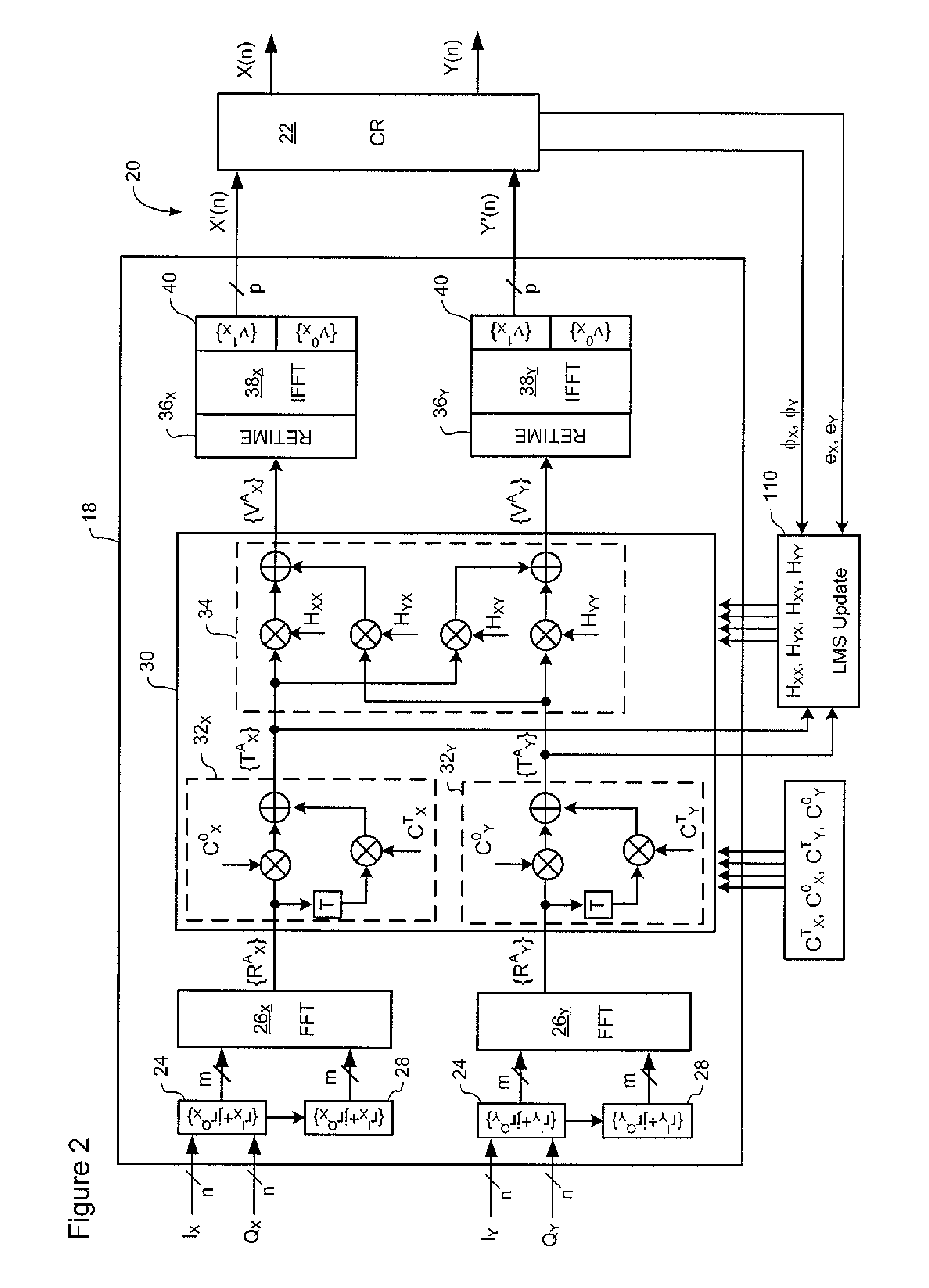
Frequency-Domain Processor (FDP)

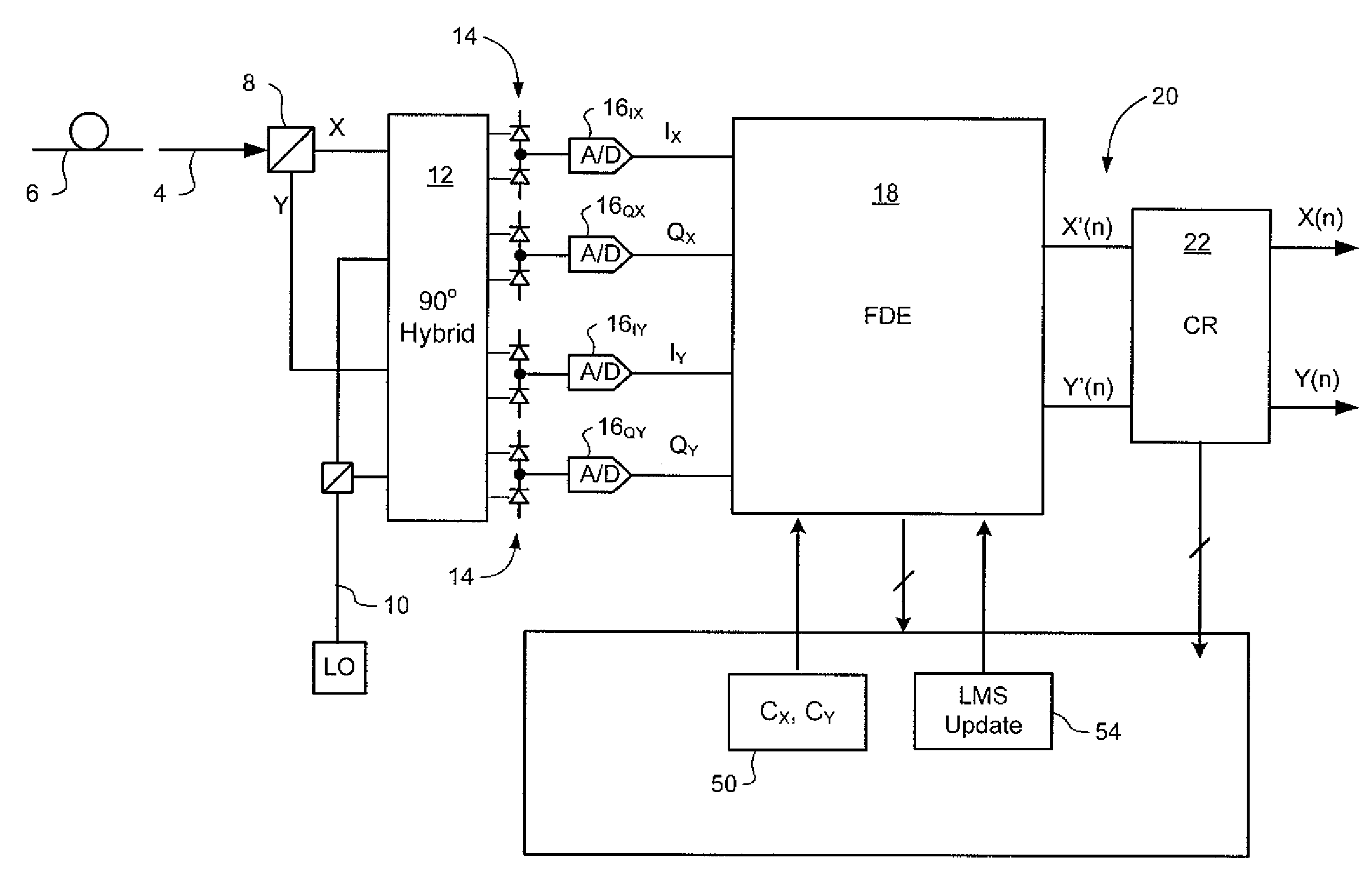
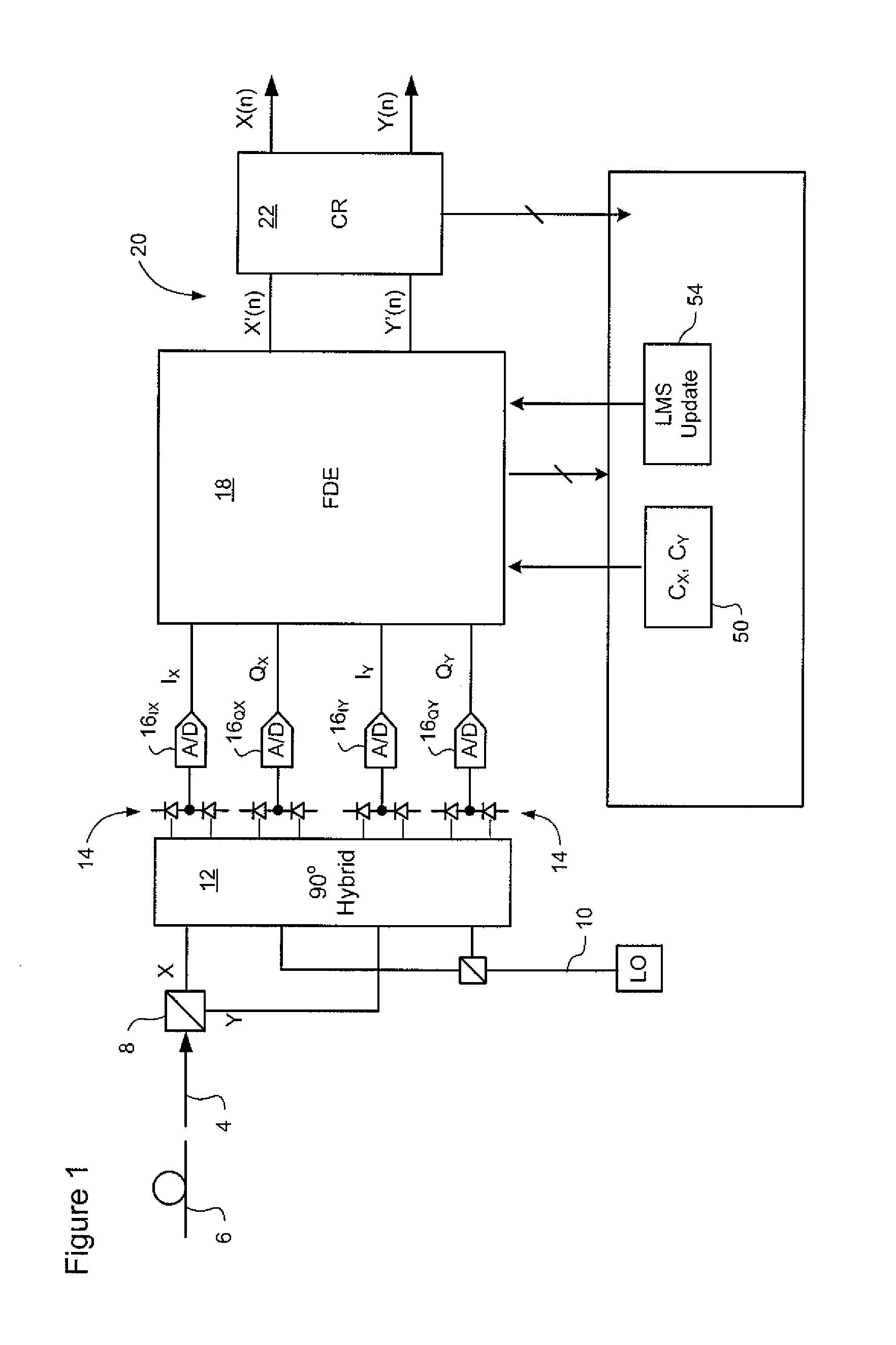
[0025]FIG. 1 illustrates principle elements of a coherent optical receiver of the type known from Applicant's co-pending U.S. patent applications Ser. No. 12 / 030,242 filed Feb. 13, 2008, in which methods in accordance with the present invention ay be implemented. As may be seen in FIG. 1, an inbound optical signal 4 received through an optical fiber link 6 is split into orthogonal received polarizations by a Polarization Beam Splitter 8. Both received polarisations are then mixed with a local oscillator (LO) signal 10 by a conventional 90° optical hybrid 12, and made incident on a set of photodetectors 14. The photodetector current output from each of the photodetectors 14 is then sampled by respective Analog-to-Digital (A / D) converters 16. The raw multi-bit digital sample streams IX, QX, and IY, QY generated by the A / D converters 16 are supplied to a signal equalizer 18. If desired, timing control methods described in Applicant's co-pending U.S. pate...

example 2

Forward Error Correction (FEC) Decoder

[0043]FIG. 7 schematically illustrates a representative technique by which Forward Error Correction (FEC) decoding can be adjusted based on changes in the IC temperature. In the embodiment of FIG. 7, the FEC decoding operation is represented by a cascade of FEC decode blocks 44a-f, which are cascaded to enable iterative decoding of sample estimates X(t) which may, for example, be supplied by the receiver described above with reference to FIGS. 1-6.

[0044]Iterative FEC decoding is known in the art. Normally, each iteration corrects some of the bit errors, and enables additional bit errors to be corrected by the next iteration. In the embodiment of FIG. 7, the conventional iterative FEC decode operation is modified to that the number of iterations that are performed can be adjusted during runtime. In the illustrated embodiment, the cascade of FEC decode blocks is divided into a first stage 46 and a second stage. The first stage (which, in the embod...


PUM


Abstract

A method of managing operation of an Integrated Circuit (IC) designed to process a signal A temperature of the IC is detected, and signal processing performed by the IC adjusted based on the detected temperature.

Description

CROSS-REFERENCE TO RELATED APPLICATIONS[0001]This is the first application filed in respect of the present invention.TECHNICAL FIELD[0002]The present invention relates to high-speed communications networks, and in particular to methods and systems for soft thermal failure in a high capacity transmission system.BACKGROUND OF THE INVENTION[0003]In the field of communications networks, telecommunications equipment is required to meet stringent availability and environmental requirements. In very general terms, telecommunications equipment (such as transmitters, receivers, routers and switches) must be able to function properly under any anticipated environmental conditions. For example, the Synchronous Optical Network (SONET) standard specifies that an OC-192 signal operate at a line rate of 9.95328 Gb / s (giga-bits / second) with a maximum permissible bit error rate (of 10-12). All SONET equipment designed to process such a signal must be able to achieve this level of performance, even i...

Claims


Application Information

Patent Timeline
IPC IPC(8): H01L35/00
CPCH03K19/00369H03K2017/0806H03M13/29H03M13/3707H03M13/2975H03M13/2987H03M13/2951
Inventor ROBERTS, KIM B.
Owner CIENA
Learn More