Short range radar small in size and low in power consumption and controlling method thereof

a short range radar and power consumption technology, applied in the field of short range radars, can solve the problems that conventional pulse radars cannot meet such a need insufficient time, and achieve the effects of low power consumption, simplified construction, and small siz

Inactive Publication Date: 2009-10-15
PANASONIC CORP +1
View PDF4 Cites 32 Cited by
  • Summary
  • Abstract
  • Description
  • Claims
  • Application Information

AI Technical Summary

Benefits of technology

[0057]With the above-described construction, according to short range radars and controlling method thereof of the present invention, a detector circuit multiplies signals obtained by branching received reflection wave signals by a branch circuit by means of a linear multiplier to obtain its square component, and samples a baseband component from its square component by means of a filter, thereby detecting a reflection wave signal. Thus, there is no need for a local signal for detection, and concurrently, its construction is simplified, making it possible to contribute to achievement of short range radars which are small in size and low in power consumption.
[0058]In addition, the short range radars and controlling method thereof of the present invention is a system of integrating power of received waves unlike a conventional correlating process, and thus, is suitable for detecting a target having a so-called large dispersion property in which a transmission pulse and a receiving pulse are greatly different from each other in waveform, such as a human body.
[0059]Further, according to the short range radars and controlling method thereof of the present invention, an osc

Problems solved by technology

However, in actuality, there are a variety of problems to be solved, which will be described later, in order to achieve short range radars having high distance resolution using this UWB.
One of the important problems is that, although there is a need fo

Method used


Image

  • Short range radar small in size and low in power consumption and controlling method thereof
  • Short range radar small in size and low in power consumption and controlling method thereof
  • Short range radar small in size and low in power consumption and controlling method thereof

Examples


first embodiment

[0080]First a description will be given with respect to a construction of short range radars according to a first embodiment of the present invention.

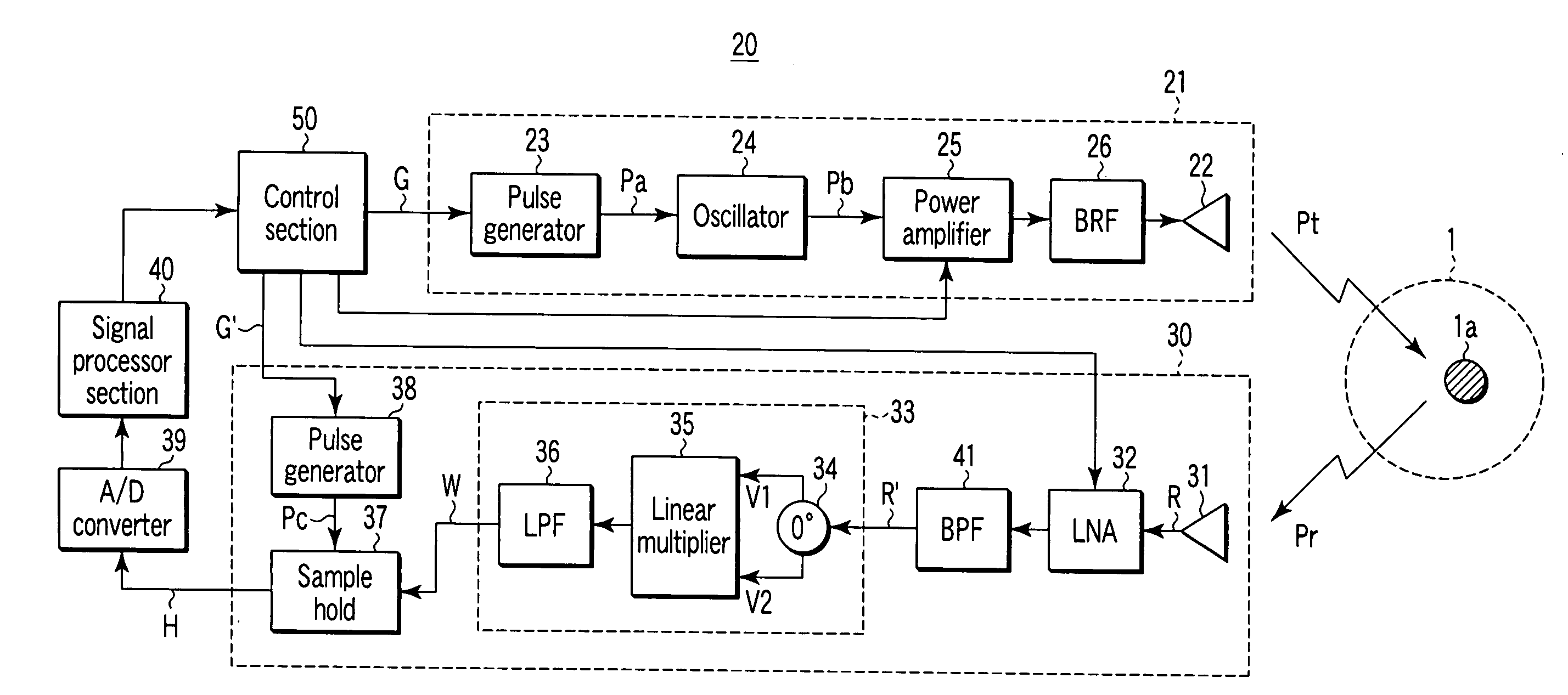
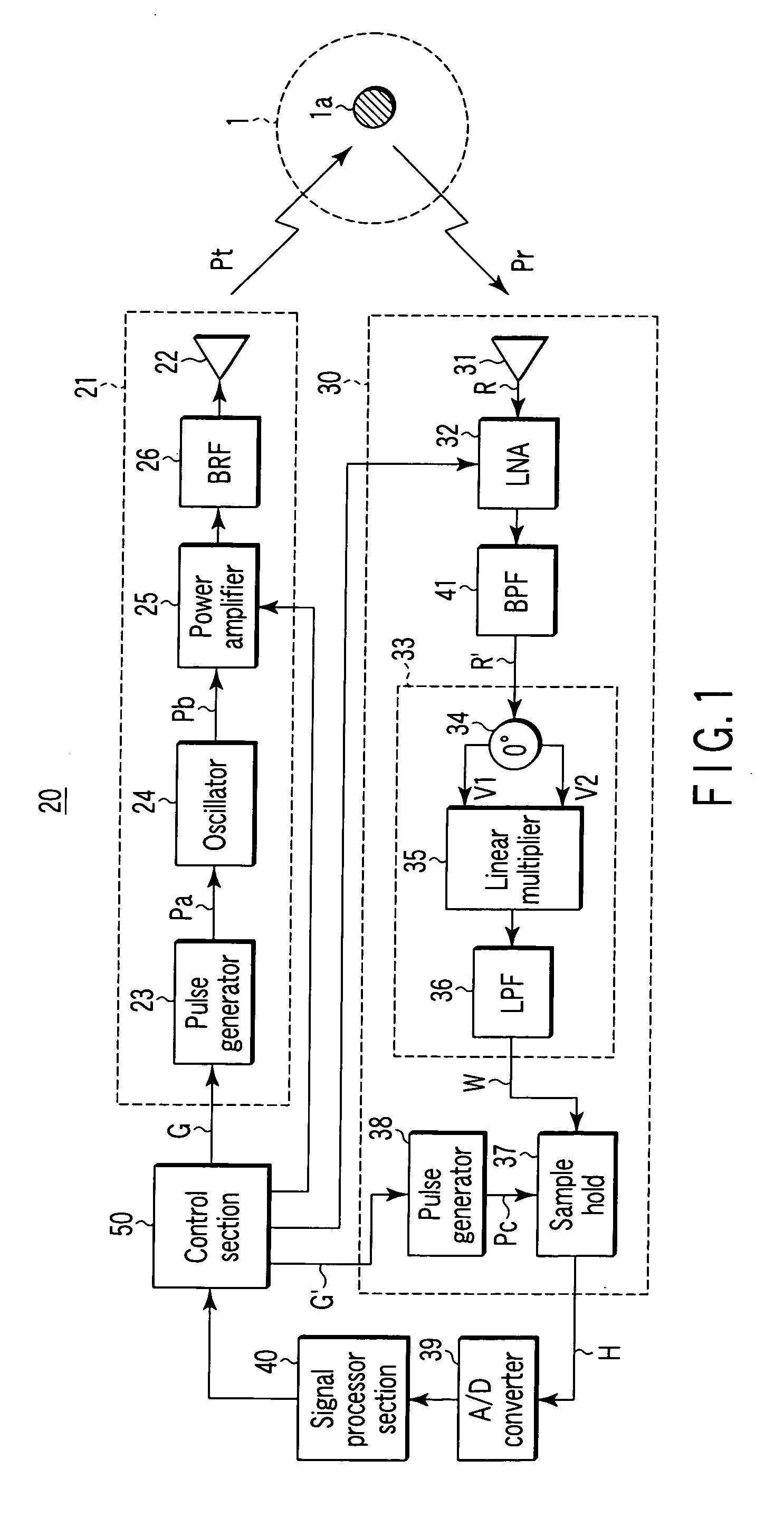
[0081]FIG. 1 is a block diagram depicting a construction of a short range radar 20 according to the first embodiment of the present invention.

[0082]The short range radar 20 according to the present invention basically includes: a transmitter section 21 which radiates a short pulse Pt to a space 1; a receiver section 30 having a detector circuit 33 composed of a branch circuit 34 which receives a reflection wave Pr of a short range wave Pt radiated to the space 1 by means of this transmitter section 21 and branches in phase a signal R′ of the reflection wave Pr into first and second signals V1 and V2, a linear multiplier 35 which linearly multiplies the first and second signals V1 and V2 branched in phase by means of this branch circuit 34, and a low pass filter 36 which samples a baseband component from an output signal from this linea...

second embodiment

[0207]FIG. 12 is a block diagram depicting a configuration of essential portions of a second embodiment of short range radars according to the present invention.

[0208]As described above, in the integration type sample hold circuit 37 according to the first embodiment, an electric discharge due to a leakage occurs, thus making it difficult to hold a voltage for a long period of time.

[0209]In such a case, as shown in FIG. 12, a plurality of sample hold circuits, in this example, four sample hold circuits 37A, 37B, 37C, and 37D and four A / D converters 39A, 39B, 39C, and 39D are provided in parallel.

[0210]In addition, for example, Pc (t), Pc (t+Te / 4), Pc (t+Te / 2), and Pc (t+3Te / 4) may be applied from a pulse generator 38′ as a plurality of pulse signals whose generation times are different from each other so that the sample hold circuits 37A, 37B, 37C, and 37D each carry out integration at their respectively different periods with respect to an output signal W of the detector circuit 33...

third embodiment

[0215]FIG. 13 is a block diagram depicting a configuration of essential portions of a third embodiment of short range radars according to the present invention.

[0216]In FIG. 13, the same constituent elements having a configuration of short range radars according to the first embodiment shown in FIG. 1 are designated by the same reference numerals. A duplicate description is omitted here.

[0217]As described above, in the short range radars according to the present invention, a linear multiplier 35 is used for a detector circuit 33, and thereby there is no need for using a local signal unlike a conventional quadrature type detector circuit for use in pulse radars. Thus, a short pulse radar 20′ in a diversity system as shown in FIG. 13 can be provided very easily.

[0218]In this short pulse radar 20′, two pairs of receiver sections 30A and 30B and two pairs of A / D converters 39A and 39B allocated in a state in which respective receiving antennas 31a and 31b are spaced from each other by a...


PUM


Abstract

A transmitter section radiates a short range wave to a space. A receiver section has a detector circuit composed of a branch circuit which receives a reflection wave of the short range wave radiated to the space by means of the transmitter section and branches in phase a signal of the reflection wave into first and second signals, a linear multiplier which linearly multiplies the first and second signals branched in phase by means of the branch circuit, and a low pass filter which samples a baseband component from an output signal from the linear multiplier. A signal processor section carries out an analyzing process of an object which exists in the space based on an output from the receiver section. A control section makes a predetermined control with respect to at least one of the transmitter section and the receiver section based on an analysis result from the signal processor section.

Description

TECHNICAL FIELD[0001]The present invention relates to short range radars and a method for controlling thereof. In particular, the present invention relates to short range radars and a method for controlling thereof employing a technique for achieving, with a simple and small sized construction, short range radars used in the range of a quasi millimeter band (UWB: Ultra-wideband) from 22 GHz to 29 GHz allocated for automotive radars or radars for walk assistance of visually handicapped persons, in particular, and achieving low power consumption, from among short range radars for radiating pulse waves of narrow width (short range waves) to a space in a predetermined cycle, receiving and detecting a reflection wave from an object which exists in the space, and analyzing the object which exists in the space based on its detected output.BACKGROUND ART[0002]A pulse radar for investigating an object in space by using conventionally known pulse waves basically has a construction as shown in...

Claims


Application Information

Patent Timeline
IPC IPC(8): G01S13/00
CPCG01S7/032G01S7/285G01S13/0209H03D7/1433H03D2200/009H03D7/165H03D2200/0025H03D2200/0043H03D2200/0088H03D7/1458
Inventor TESHIROGI, TASUKUUCHINO, MASAHARUSAITO, SUMIOEJIMA, MASANORI
Owner PANASONIC CORP
Why Eureka
Try Eureka