Apparatus for solid-oxide fuel cell shutdown

a technology of solid-oxide fuel cell and apparatus, which is applied in the field of apparatus for solid-oxide fuel cell shutdown, can solve the problems of failure of sofc stack, deterioration of sofc stack, and so as to prevent degrading and fatiguing oxidation of anodes, reduce the volume of reducing fluid required per shutdown, and reduce the effect of fluid flow

Active Publication Date: 2009-10-15
APTIV TECH LTD
View PDF8 Cites 5 Cited by
  • Summary
  • Abstract
  • Description
  • Claims
  • Application Information

AI Technical Summary

Benefits of technology

[0013]Briefly described, an apparatus and method for an emergency shutdown of a SOFC system enables prevention of the degrading and fatiguing oxidation of the anodes of the stack in the event that a sudden and complete system shutdown is necessary.
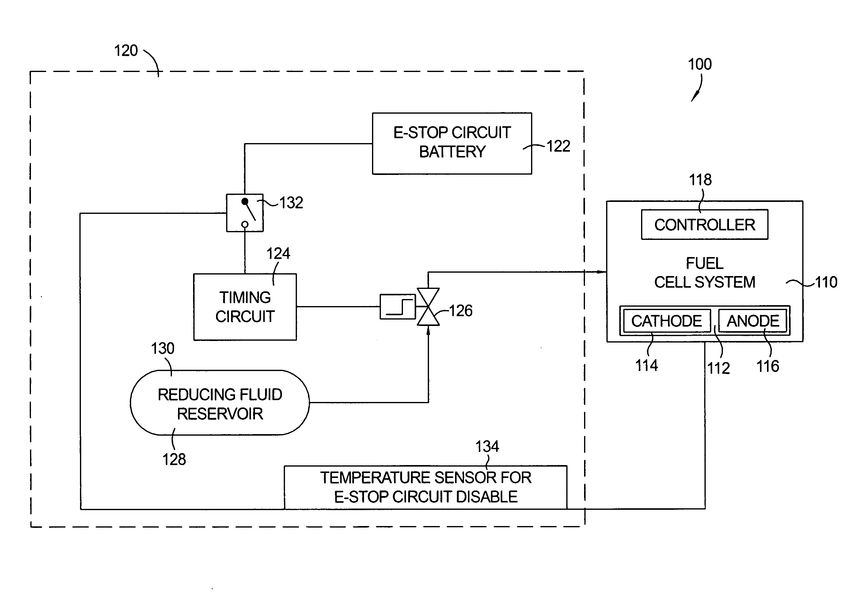
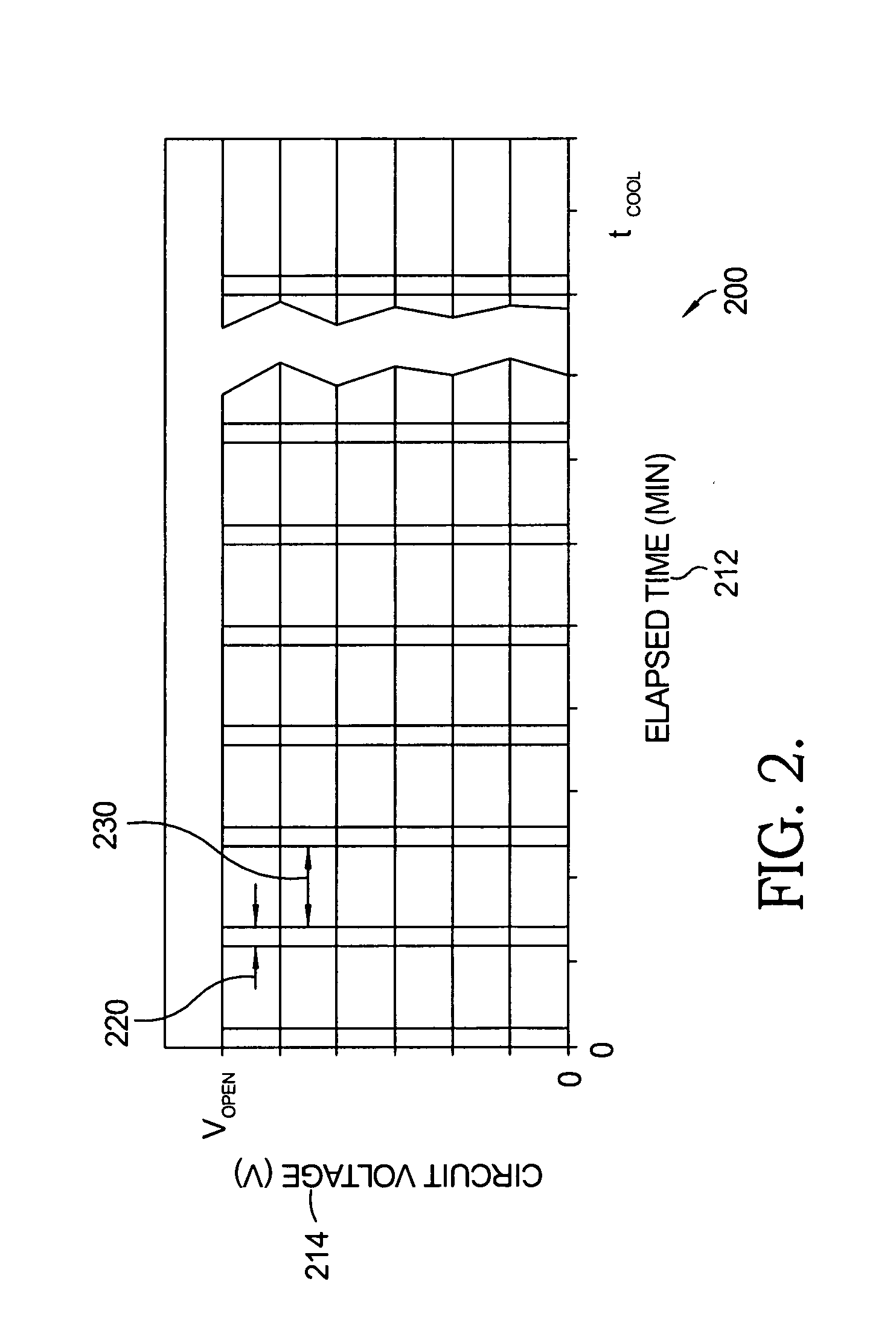
[0014]The unique and novel apparatus utilizes a battery, a timing circuit, a temperature sensor, a reservoir containing a reducing fluid, and a valve. In order to control the flow of reducing fluid to the stack of the SOFC system, the valve is controlled by the timing circuit. Upon a system emergency shutdown, the timing circuit will be enabled and will pulse the valve, allowing an intermittent flow of the reducing fluid. For a prescribed period of time the valve is opened allowing the flow of reducing fluid, and then the valve is closed, blocking the flow of reducing fluid for a prescribed period of time. This flow pulsation may continue until the temperature sensor, located within the system, reaches a prescribed set point that preferably lies below the critical temperature for anode oxidation, or until the reducing fluid reservoir is empty. It is not necessary for the reducing fluid flow to be cut off once the desired temperature of the system is reached. However, a reservoir of reducing fluid may be used multiple times on a single filling if it can be shut off once a safe temperature is achieved. By intermittently providing a reducing fluid to the anode side of the fuel cell stack, the volume of the reducing fluid required per shutdown can be reduced compared to prior art continuously flowing systems, while an oxygen free environment surrounding the anodes of the stack can be maintained.
[0015]Another advantage of the apparatus for an emergency system shutdown in accordance with the invention is the ability to operate independently of the main power plant. The apparatus does not require any active control from the SOFC system, and therefore can be used in an immediate emergency shutdown situation. The disclosed apparatus is entirely a stand-alone component that may be added to any conventional SOFC system. The apparatus in accordance with the invention can be recharged, allowing the same hardware to be used over and over, however, a disposable unit could be used if found to be desirable.

Problems solved by technology

Due to the relative high operating temperature of the SOFC stack, typically about 750° C. and higher, and the chemical composition of the anodes, purging the entire SOFC stack with cathode air for cooling prior to extended periods of nonuse results in a degrading and fatiguing oxidation of the anodes since oxygen is allowed in the cavities adjacent to the anodes.
At temperatures above about 400° C., and in the presence of free oxygen, nickel oxide is formed, which may lead to deterioration of the SOFC stack and which over time may cause failure of the SOFC stack.
Therefore, it is harmful to the SOFC stack when oxygen is allowed in the cavities adjacent to the plurality of anodes.
While purging the anode side of the stack during a normal cooling process with a reducing fluid produced by the SOFC system itself, such as utilization of exhaust gas where oxygen has been reduced below ignition concentration, has been proposed, this is not a solution for emergency system shutdowns when an unexpected event requires an immediate shutdown of the entire SOFC system including the use of external power.
In such emergency situation, the SOFC system does not have time to execute its normal shutdown process and the anode components of the stack cannot be protected from detrimental oxidation.
No protecting mechanisms for the anode side of the stack are currently known for such emergency situation.

Method used


Image

  • Apparatus for solid-oxide fuel cell shutdown
  • Apparatus for solid-oxide fuel cell shutdown
  • Apparatus for solid-oxide fuel cell shutdown

Examples


Embodiment Construction

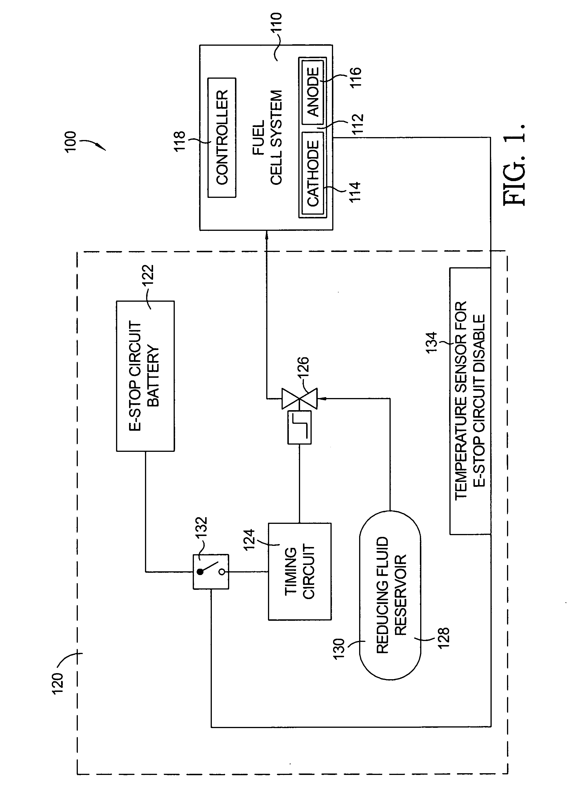
[0020]Referring to FIG. 1, a schematic mechanization diagram of a Solid-Oxide Fuel Cell (SOFC) power plant 100 in accordance with the invention shows a SOFC system 110 and an emergency shutdown apparatus 120.

[0021]The SOFC system 110 includes at least one SOFC stack 112 as well as auxiliary equipment and controls. SOFC stack 112 includes a plurality of solid-oxide fuel cells stacked together in electrical series. Each of the fuel cells includes a cathode 114 and an anode 116, the plurality of cathodes 114 forming the cathode side of stack 112 and the plurality of anodes 116 forming the anode side of stack 112. Because each anode 116 and cathode 114 must have a free space for fluid passage over its surface, the cathode side and the anode side of stack 112 are typically separated by perimeter spacers which are selectively vented to permit fluid flow to the anodes 116 and cathodes 114 as desired but which also form seals on the axial surfaces to prevent fluid leakage from the cathode s...


PUM

PropertyMeasurementUnit
temperaturesaaaaaaaaaa
operating temperatureaaaaaaaaaa
temperatureaaaaaaaaaa

Abstract

An emergency shutdown apparatus for a solid-oxide fuel cell system, including a fuel cell stack, comprises a reservoir containing a reducing fluid, a valve enabling or preventing flow of the reducing fluid from the reservoir to the fuel cell stack, a timing circuit operating and controlling the valve, and a battery powering the timing circuit. The apparatus for an emergency system shutdown is able to operate independently of the main power plant and does not require any active control from the solid-oxide fuel cell system. The disclosed apparatus is entirely a stand-alone component that may be added to any conventional solid-oxide fuel cell system. The apparatus in accordance with the invention can be recharged, allowing the same hardware to be used over and over, however, a disposable unit could be used if found to be desirable.

Description

RELATIONSHIP TO GOVERNMENT CONTRACTS[0001]The present invention was supported in part by a U.S. Government Contract, No. DE-FC2602NT41246. The United States Government may have rights in the present invention.TECHNICAL FIELD[0002]The present invention relates to fuel cells having a solid-oxide electrolyte layer separating an anode layer from a cathode layer; more particularly, to fuel cell assemblies and systems including a plurality of individual fuel cells in a stack wherein oxygen and reformed fuel are supplied to the stack; and most particularly, to an apparatus for shutdown of a solid-oxide fuel cell system and a method for anode oxidation prevention within the stack during an emergency system shutdown.BACKGROUND OF THE INVENTION[0003]Fuel cells, which generate electric current by the electrochemical combination of hydrogen and oxygen, are well known. In one form of such a fuel cell, an anodic layer and a cathodic layer are separated by an electrolyte formed of a ceramic solid ...

Claims


Application Information

Patent Timeline
Patent Type & Authority Applications(United States)
IPC IPC(8): H01M8/04H01M8/10H01M8/02
CPCH01M8/04223H01M8/04231H01M8/04365H01M8/04753H01M8/04955Y02T90/32H01M2250/20H01M8/04007Y02E60/50Y02E60/525H01M2008/1293H01M8/04228H01M8/04303Y02T90/40
Inventor MERGLER, CHRISTOPHER M.KELLY, SEAN M.
Owner APTIV TECH LTD
Why Eureka
Try Eureka