The location at which the shaft enters the equipment is a potential point of leakage.
There is usually
continuous leakage through the
stuffing box, and this sealing method can only be used for reactors of non-hazardous liquids at atmospheric or low pressures.
Considerable power can be lost in friction at the
stuffing box.
Mechanical seals have barrier fluids that can leak in case of seal failures.
Mechanical seals can fail in several ways.
The most common cause is failure of seal elastomers caused by mechanical damage to the faces, mechanical shock, improper alignment, vibration, etc. leading to leakage across the seal face.
In these cases, there is loss of vessel fluids, and / or
contamination of vessel contents with seal liquids.
Pressures and temperatures are higher, and generally, process fluids are more hazardous.
Due to this reason, mechanical seal failure can seriously compromise
plant safety, and can also result in environmental hazards.
Also, pumps generally consume low power, as they have small size impellers.
Due to their high speeds, typically 3000 RPM, torque requirements are low.
Hitherto, there has been considerable difficulty in using magnetic seals for
agitator and similar drives, for the following reasons.
Power consumption is relatively high, and speeds are low, usually below 300 RPM, hence torque requirements are substantially higher in Reactors.
A drawback of this invention is that the sleeve bearings are prone to freezing at low temperatures, thereby necessitating circulation of heating fluids around the sleeves.
Another drawback is that there is considerable heat generated by friction in the operation of the invention.
The end of the
agitator shaft which is immersed in process liquid, which may be corrosive, and can also have suspended
abrasive solids, can erode an immersed bearing or the shaft itself.
There are some other limitations on the currently available magnetic seals for reactors.
One limitation is regarding the size of the reactors.
Another limitation is regarding the shaft
diameter.
The limitations on the shaft
diameter and the mixing volume also mean that the currently available magnetic seals cannot be deployed on
industrial scale applications where the mixing volumes can be 2 cubic meters to 25 cubic meters or up and torque requirements can be as high as 2000 Nm or more.
a) Centrifugal pumps operate at high speeds, typically around 3000 RPM. (For a given
horsepower, torque is inversely proportional to RPM). Hence, a medium size (10 HP)
centrifugal pump will have a steady-state torque rating of 24 Newton-metres (N-m). As torques are low, shaft sizes as well as
magnet assemblies are correspondingly small. Hence, the outer
magnet assembly is quite small, of the order of 10 cm
diameter and 8 cm long. Such small assemblies can be directly mounted on motor shafts, without any fear of eccentric motion (wobbling).The inner pump assembly is an
impeller attached to a shaft, fitted with inner magnets. The shaft is supported at either end into
ceramic sleeves fitted in the pump casing. These sleeves act as bearings, and keep the pump shaft / impeller / inner
magnet assembly aligned in the pump casing. The pump is always operated in “primed” condition, i.e., when it is flooded with the liquid to be pumped. This fluid removes frictional heat generated in the sleeve bearings, and keeps them cool.
b) Lab scale reactors are fitted with fractional HP motors (less than 1 HP), and typically operate at 500 to 1000 RPM. The
maximum torque for such reactors is 10 to 15 N-m. Shaft sizes are small, say 1 to 2 cm diameter. Equipment for such low torques require miniscule magnetic drives. As in the case of centrifugal pumps, the outer magnet assembly is coupled to the
motor shaft. Its small size and low weight precludes any chances of wobbling. The Shaft, which hangs at the top, is very light, about a few grams. As a result, axial and radial loads are extremely low, hence, the shaft is supported (prevented from falling into the lab reactor) by means of
ceramic or elastomeric bushes at its upper end.
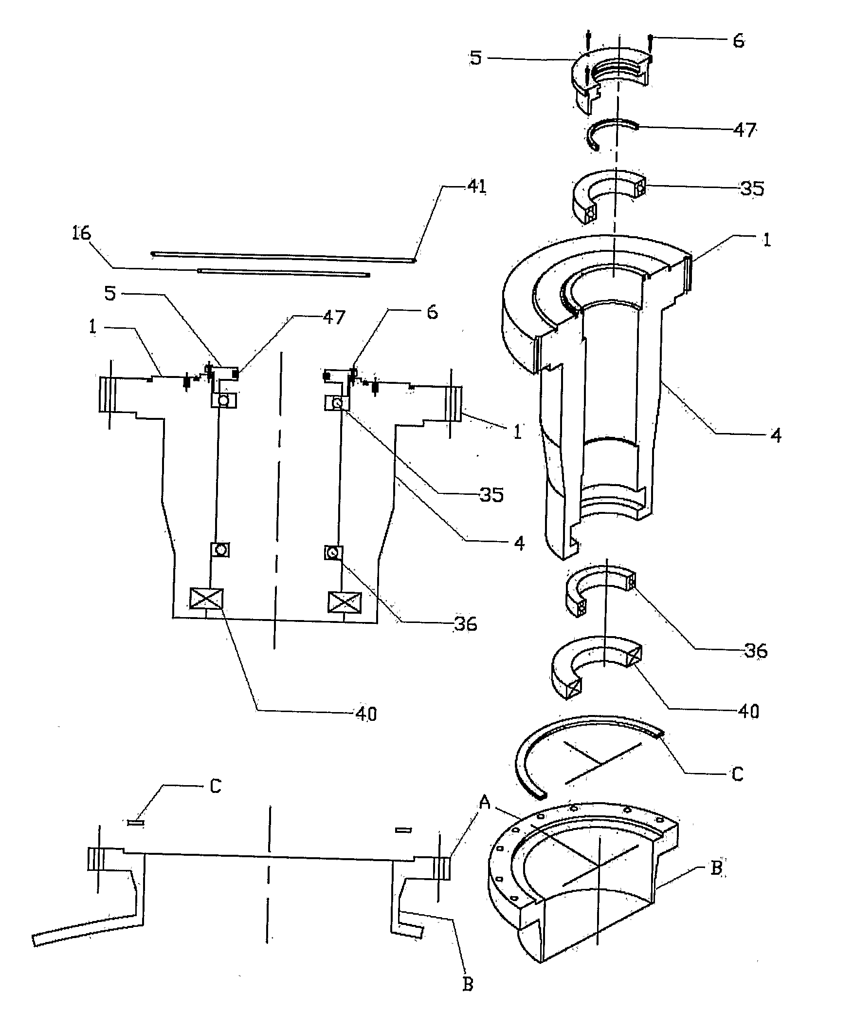
On the other hand, magnetic seals for Industrial Reactors / Autoclaves require substantially higher torque.
Higher torques require substantially higher inner and outer magnet assemblies, and obviously larger shrouds.
It is not possible to scale up existing designs in a linear manner, for the following reasons:1) Magnetic seals in Industrial reactors are likely to be used to contain hazardous vapours / gases, or withstand high internal pressures, or prevent
contamination of reactor contents, or a combination of these.
This, in turn, makes it necessary to provide larger / more magnet assemblies, requiring even larger shrouds.2) Inner bearings cannot be sleeves (like
ceramic /
elastomer sleeves for lab reactors / pumps), as sleeves cannot bear
high weight of inner shafts.
Also, inner bearings cannot be at either ends of the shaft, as, at the lower end, the shaft / impeller is immersed in the reactor liquid being mixed.
This results in an upward thrust on the shaft.
These solvents can also
attack lubricants, even in “sealed” bearings.
Also, many chemical reactors are subjected to vacuum.
This can force
grease to ooze out of bearings.
This phenomenon is absent in lab reactors & pumps, where the sleeve bearings prevent ingress of solids.7)
Internal pressure or vacuum can result in severe axial loads on reactor shafts.
For example,
internal pressure of 25 atmospheres on a 10 cm diameter shaft can result in upward bearing load of almost 2 tons.
It is not possible to scale up existing (small sized) magnetic seal designs in a straightforward manner.
For these reasons, magnetically sealed agitators have not been widely used till now, particularly in the corrosive and
abrasive environments or
high pressure applications, especially on industrial scales.

