Material for surgical use in traumatology

a traumatology and surgical technology, applied in the field of traumatology surgical use materials, structure and methods, can solve the problems of local osteoporosis, loosening, fatiguing or breaking of plates, and undesirable risks and costs

Inactive Publication Date: 2009-10-22
EFSKIND LASSE DANIEL +1
View PDF16 Cites 3 Cited by
  • Summary
  • Abstract
  • Description
  • Claims
  • Application Information

AI Technical Summary

Problems solved by technology

As the fracture heals, a large proportion of these devices must be removed with a second surgery that poses undesirable risks and costs.
Additionally, the rigidity of many internal fixation devices may pose problems during healing.
Commonly used plates of metal and metal alloys actually tend to be too rigid as they do not have the same elasticity as bone, resulting in loosening, fatiguing, or breaking of the plates.
Plates left in position after healing of the fracture can cause local osteoporoses and, hence, weakening of the bone.
Plates and screws may also cause soft tissue irritation or progressive foreign body reactions when kept in place for long periods of time after bone healing.
These materials are not entirely satisfactory, however, because they gradually weaken and the rate of absorption or dissolution cannot be actively controlled in vivo.
Hence, the time and duration of fixation with bioabsorbable materials cannot be varied or controlled in vivo, which often is necessary as healing time varies widely from patient to patient and is difficult to predict.
In this manner, in vivo control over the rate of disintegration of the polymer is not permitted.
Although the triggered disintegration eliminates the time uncertainty of naturally bioerodible materials from one patient to the next, there is inherent uncertainty in administering the triggering agent, whether by diet, direct local application, parenteral feeding, etc.
Also, these materials do not have sufficient strength to be used in fracture healing, and it is generally impractical or impossible to inject a chemical trigger to the entire surface of plates and screws in vivo.
However, due to the high pressure, this solution is vulnerable to fatal leakages during the up to 18-month-long healing process.

Method used


Image

  • Material for surgical use in traumatology
  • Material for surgical use in traumatology
  • Material for surgical use in traumatology

Examples


Embodiment Construction

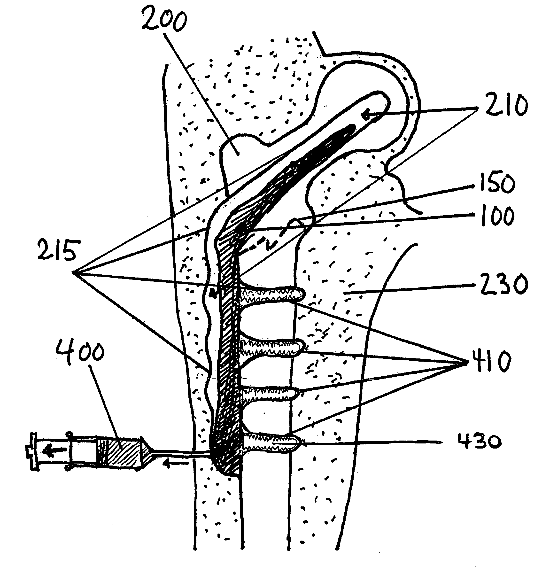
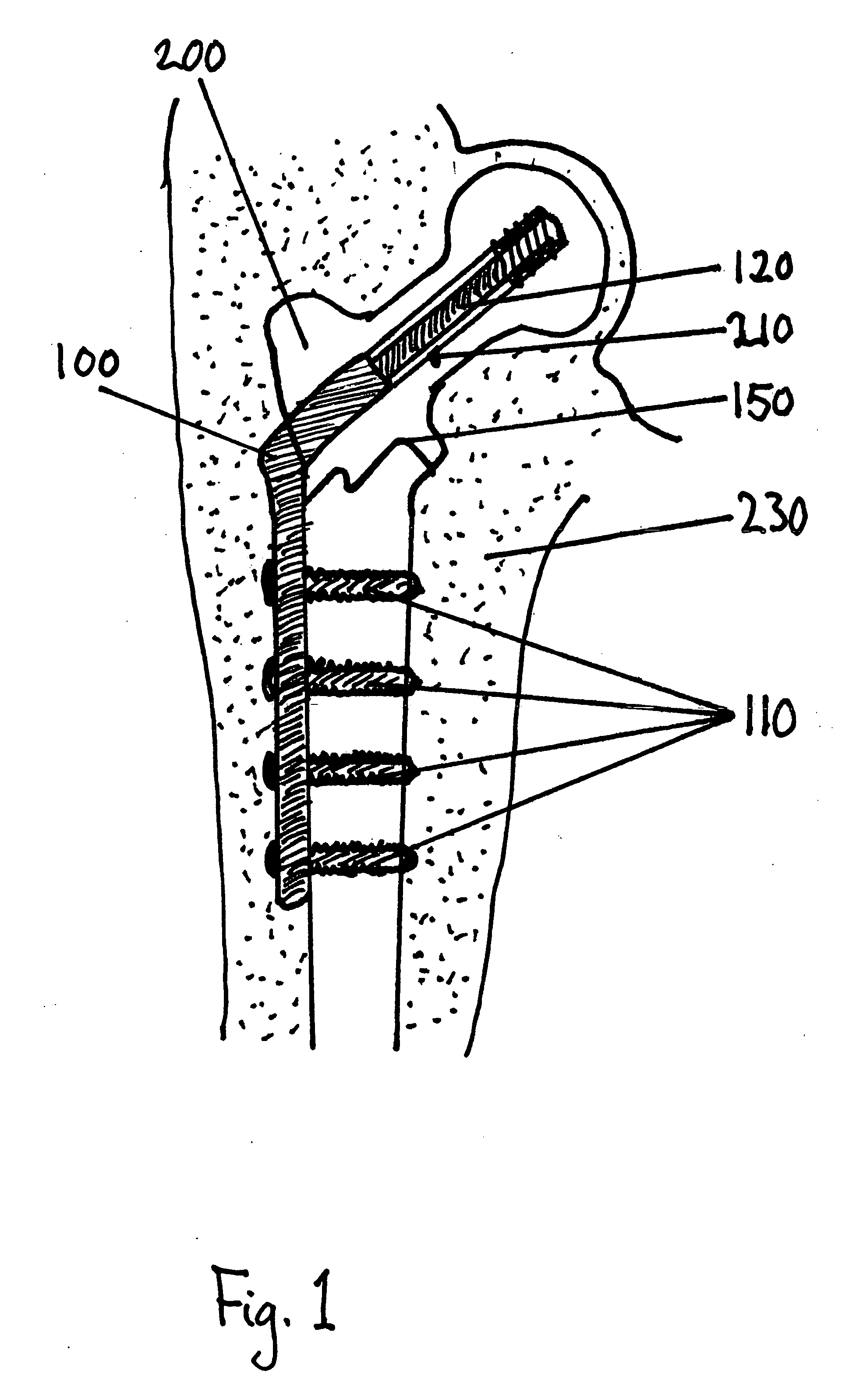
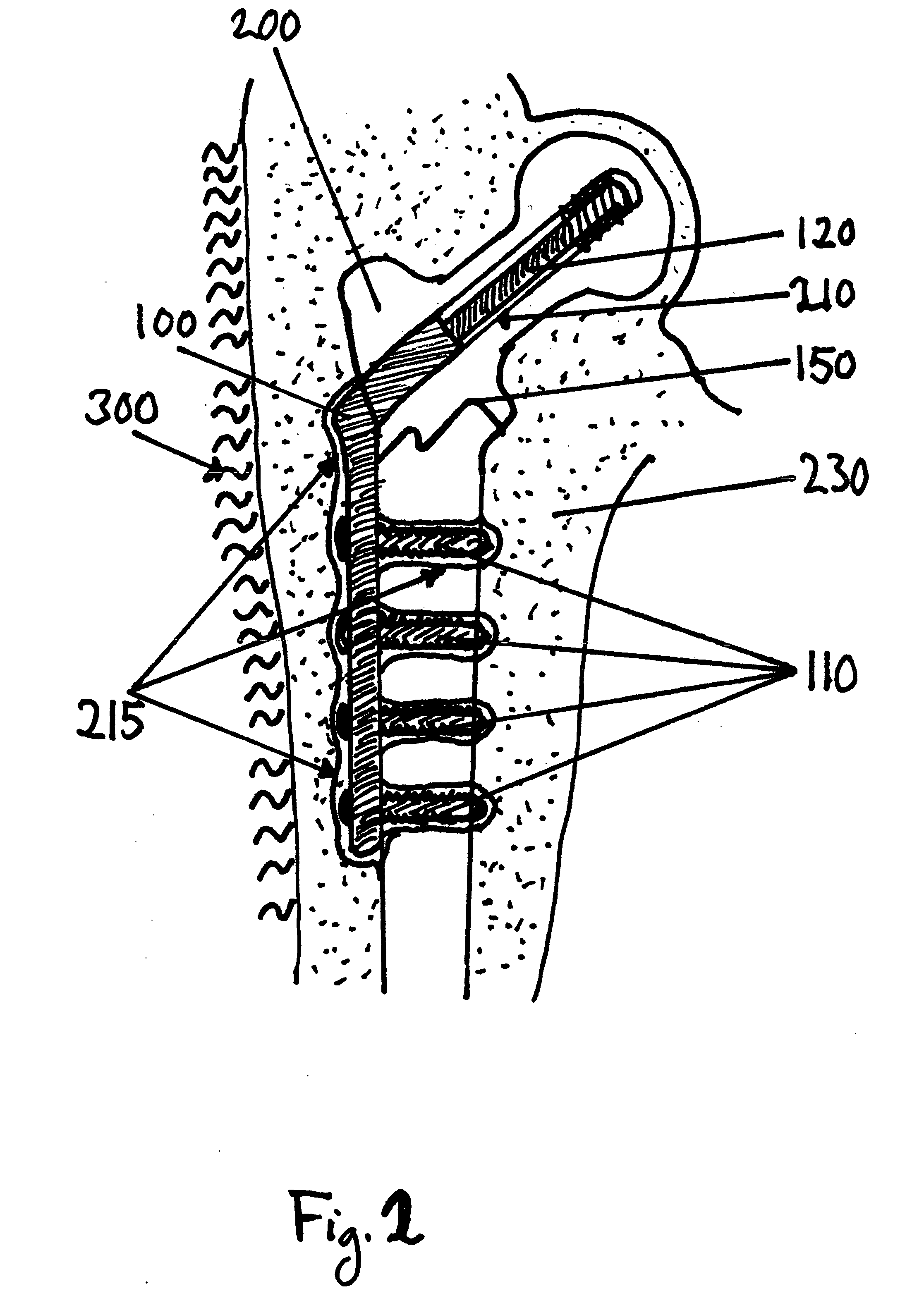
[0023]This description of preferred embodiments is intended to be read in connection with the accompanying drawings, which are to be considered part of the entire written description of the invention. The drawing figures are not necessarily to scale and certain features of the invention may be shown exaggerated in scale or in somewhat schematic form in the interest of clarity and conciseness. In the description, relative terms such as “horizontal,”“vertical,”“up,”“down,”“top” and “bottom” as well as derivatives thereof (e.g., “horizontally,”“downwardly,”“upwardly,” etc.) should be construed to refer to the orientation as then described or as shown in the drawing figure under discussion. References to axial dimensions and directions (e.g., in an “X” direction, over a “Y” dimension, etc.) should also be construed to refer to the orientation as then described or as shown in the drawing figure under discussion. These relative terms are for convenience of description and normally are not...


PUM

PropertyMeasurementUnit
temperatureaaaaaaaaaa

Abstract

The present invention relates to a material, structure, and method for surgical use in traumatology. More particularly, the present invention relates to a composite material, a temporary biocompatible support structure, and related methods of use of the same in aiding osteosynthesis during healing of a bone fracture. The material keeps its strength in a solid phase in vivo and, to aid removal upon healing, can be transformed into a substantially fluid phase, including, for example, a pulverized state, by the application of energy at a chosen time.

Description

FIELD OF THE INVENTION[0001]The present invention relates to a material, structure, and method for surgical use in traumatology. More particularly, the present invention relates to a composite material, a temporary biocompatible support structure, and related methods of use of the same in supporting the healing process of bone fractures.BACKGROUND OF THE INVENTION[0002]Plates, nails, and other structures of various materials are widely used around the world today in bone fracture surgery and healing. Typically, such internal fixation devices are inserted during a first surgery to maintain stability and alignment during the healing process of the fracture. As the fracture heals, a large proportion of these devices must be removed with a second surgery that poses undesirable risks and costs.[0003]Additionally, the rigidity of many internal fixation devices may pose problems during healing. Commonly used plates of metal and metal alloys actually tend to be too rigid as they do not have...

Claims


Application Information

Patent Timeline
Patent Type & Authority Applications(United States)
IPC IPC(8): A61L27/46B82B1/00
CPCA61L2430/02A61L27/44
Inventor EFSKIND, LASSE DANIELIDSOE, TORE ETHOLM
Owner EFSKIND LASSE DANIEL
Why Eureka
Try Eureka