Clean, high density, soft-accumulating conveyor

a conveyor and high density technology, applied in the direction of mechanical conveyors, rolling conveyors, instruments, etc., can solve problems such as frictional particulates

Inactive Publication Date: 2009-10-29
MIDDLESEX GEN INDS MESNE
View PDF10 Cites 18 Cited by
  • Summary
  • Abstract
  • Description
  • Claims
  • Application Information

AI Technical Summary

Benefits of technology

[0014]A first belt-driven conveyor includes a flat, thin belt in combination with crowned hysteresis driving wheels and flanged idler wheels. Each driving wheel is structured and arranged to drive and center the flat, thin belt while the idler wheels are structured and arranged to laterally confine the work piece or the object carrying the work piece using the flanges on the idler wheels. A magnetic hysteresis clutch or coupling allows the driving wheels for the belt to disengage from the drive shaft of the motor whenever the inertia of a work piece or object carrying a work piece does not permit synchronization of the work piece or the object carrying the work piece with the drive speed during acceleration or deceleration. Indeed, the clutch setting is pre-programmed or keyed so that it does not exceed the friction force between the belt and the work piece or the object carrying the work piece. When the acceleration exceeds this setting, the work piece or the object carrying the work piece is decoupled from the motor.

Problems solved by technology

As a result, any difference in the velocities of two surfaces on the flange that contact the work piece or object carrying the work piece may result in undesirable rubbing and resulting frictional particulation.
The center of the crown radius machined on the driving wheels and on the return idler wheels, however, is slightly offset relative to the centerline of the belt by a distance x. This offset centers the L-shaped belts whose belt dimensions, e.g., the cross-section, are not uniform.

Method used


Image

  • Clean, high density, soft-accumulating conveyor
  • Clean, high density, soft-accumulating conveyor
  • Clean, high density, soft-accumulating conveyor

Examples


Embodiment Construction

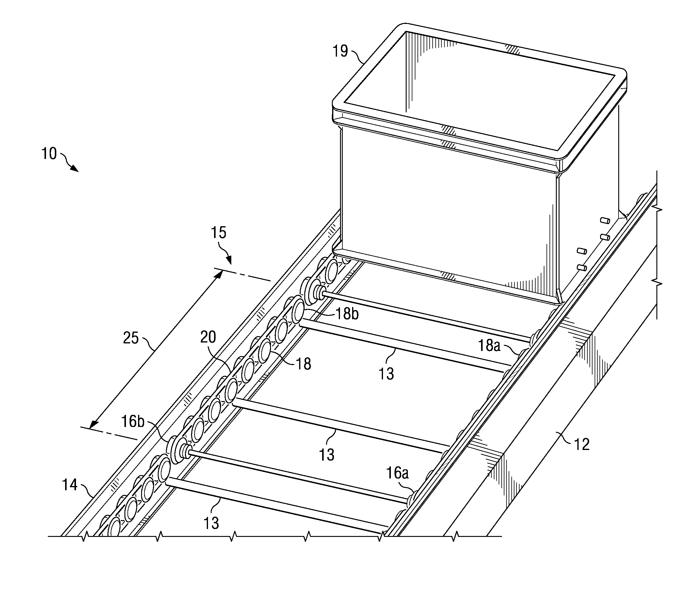
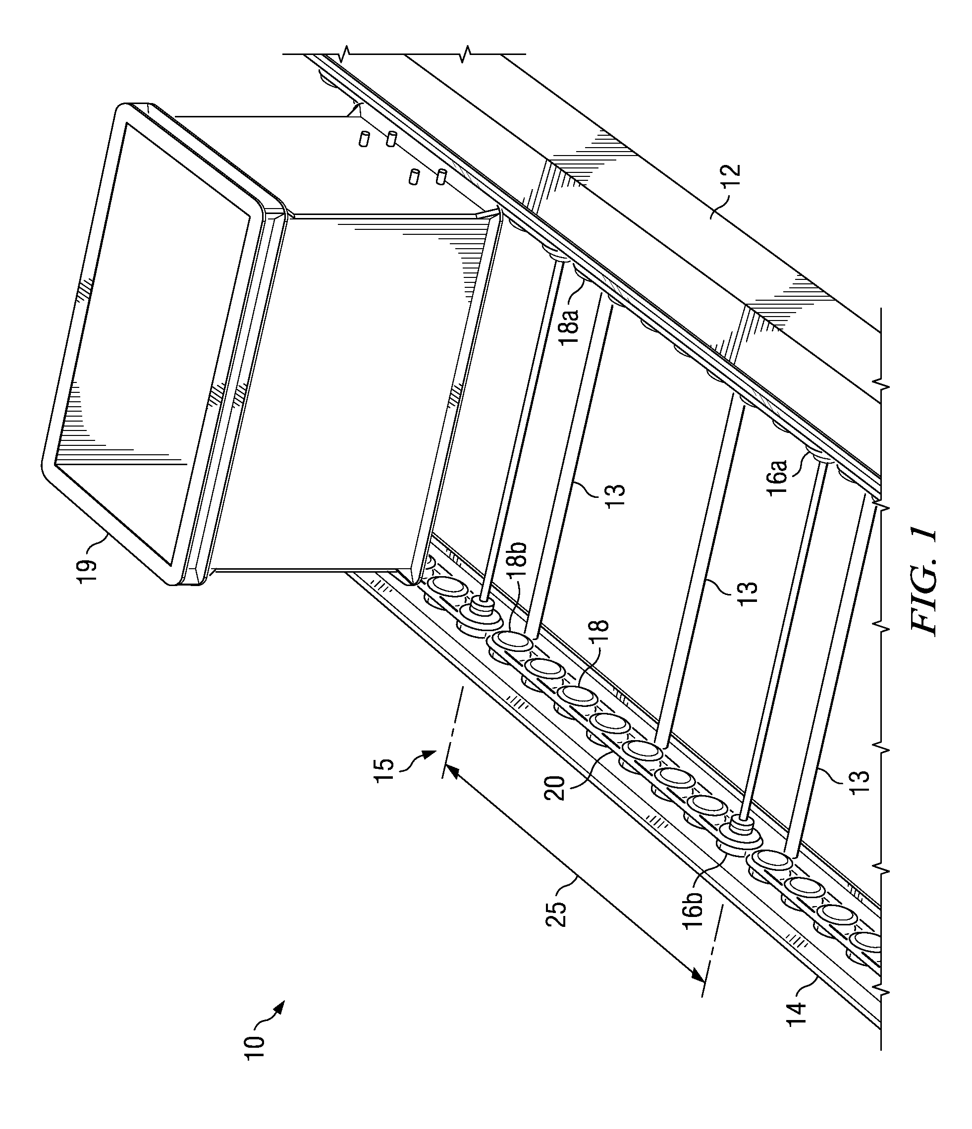
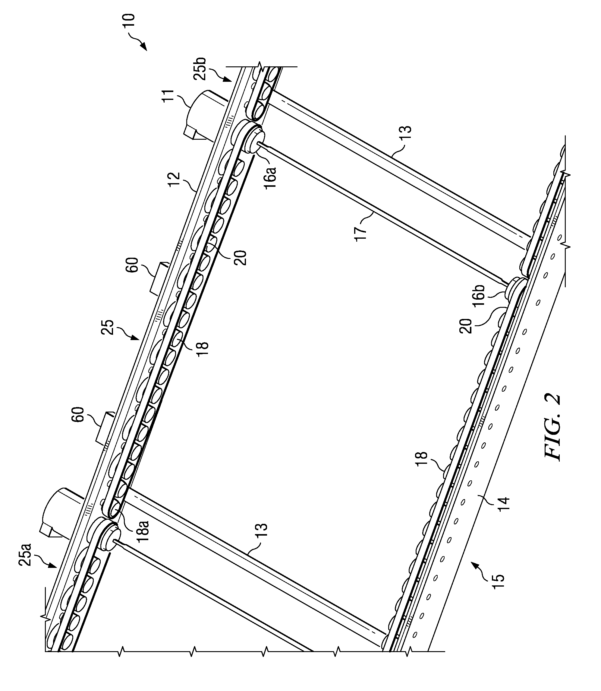
[0029]Referring to FIGS. 1 and 2, a belt-driven conveying system (“conveyor”) will be described. The conveyor 10 includes a multiplicity of interconnected conveyor modules 15 having at least one belt-driven conveyor segment 25. The belt segments 25 and conveyor modules 15 can be structured and arranged in a myriad of patterns to satisfy local transportation and plant requirements. Each conveyor module 15 is internally segmented into unit length zones or belt segments 25, whose size (length and width) is determined by the dimensions of the work piece or by the object carrying a work piece 19. Indeed, the length of a conveyor module 15 is an integer multiplier of the length of each belt segment 25 within that module 15.

[0030]For example, if the dimension of the work piece or object carrying the work piece 19 is 0.5 meters in length and the conveyor module 15 is approximately two meters in length, a total of four autonomous, belt-driven conveyor segments 25, which are each slightly lar...


PUM


Abstract

A conveyor for clean manufacturing applications. The conveyor comprises interconnected conveyor modules, each of which includes a conveyor belt segment (s). Each conveyor belt segment includes a pair of side rails that are in parallel or substantially in parallel to each other; a pair of autonomous, belt-drives for transporting work pieces or objects carrying work pieces from a proximal end of the belt segment to a distal end of the belt segment; a pair of driving wheels for turning the belt-drives, and a motor for directly or indirectly driving each of the pair of driving wheels. One of the driving wheels is mechanically or magnetically coupled to a magnetic hysteresis clutch that allows the driving wheels to disengage from the drive shaft of the motor if the inertia of the work piece does not permit synchronization of work piece with the drive speed of the motor during acceleration or deceleration.

Description

CROSS REFERENCE TO RELATED APPLICATIONS[0001]The present utility patent application claims the benefit of priority through U.S. Provisional Patent Application No. 61 / 125,901 dated Apr. 29, 2008 entitled “Clean, High Density, Soft-Accumulating Conveyor”.STATEMENT REGARDING FEDERALLY SPONSORED RESEARCH OR DEVELOPMENT[0002](Not applicable)BACKGROUND OF THE INVENTION[0003]In some industrial applications of conveyors there are a number of special performance requirements in addition to common parameters such as speed, weight, and transport capacity. Such applications can be found in the Semiconductor, Pharmaceutical, Solar Cell, Hard Disk Drive, Flat Panel Display, and other manufacturing industries. For these applications and other similar applications, the conveyors used for inter-tool movement of Work In Process (WIP), require “Particulate Free Cleanliness”, “Vibration Free Transport”, “Very High Density WIP Flow”, and “Asynchronous Movements of Pallets with Soft-Accumulation of WIP” ...

Claims


Application Information

Patent Timeline
Patent Type & Authority Applications(United States)
IPC IPC(8): B65G15/22G06F7/00
CPCB65G47/261B65G13/06
Inventor HORN, GEORGE W.
Owner MIDDLESEX GEN INDS MESNE
Why Eureka
Try Eureka