Optical sheet for backlight, backlight, and display device

a technology of optical sheets and backlights, applied in the field of optical sheets for backlights and backlights, can solve the problems of bright point or dark point on the display, triangular cross section of the prism pl, easy damage to the display, etc., and achieve the effect of improving the front side brightness, reducing the number of side lobes, and restrainting the side lobe ligh

Inactive Publication Date: 2009-10-29
HITACHT MAXELL LTD
View PDF2 Cites 16 Cited by
  • Summary
  • Abstract
  • Description
  • Claims
  • Application Information

AI Technical Summary

Benefits of technology

[0076](2) Prevention of Side Lobe Light
[0077]The optical sheet 30 restrains side lobe light from being generated using the optical reflection layer 32. With reference to FIG. 7, assume that in the conventional lenticular lens sheet, light R3 with a wide angle to the optical axis (hereinafter referred to as “wide angle light”) comes into the cylindrical lens 341. In this case, the wide angle light R3 is incident to the cylindrical surface of another cylindrical lens 342 adjacent to the cylindrical lens 341 and emitted as side lobe light R4 with a wide angle to the optical axis. The wide angle light R3 is likely to form the side lobe light R4.
[0078]With the optical sheet according to the embodiment, the wide angle light R3 comes into the surface of a through groove 321 as shown in FIG. 8 and diffused and reflected into the cylindrical lens 33. Therefore, the wide angle light R3 does not come into another adjacent cylindrical lens 33 as denoted by the dotted line in FIG. 8. Therefore, the side lobe light can be restrained.
[0079](3) Use of Reflected Light in Optical Reflection Layer
[0080]The optical reflection layer 32 not only restrains the side lobe light but also improves the front side brightness by emitting the wide angle light R3 as parallel light. As described above, the wide angle light R3 is diffused and reflected at the surface of the through groove321, while the diffused and reflected light includes light R31 incident to the cylindrical surface of the cylindrical lens 33 as shown in FIG. 8. Hereinafter, light such as the light R31 will be referred to as indirect incident light R31. The indirect incident light R31 includes light emitted as parallel light R10. Therefore, the optical reflection layer 32 not only restrains wide angle light from being emitted as side lobe light but also emits the wide angle light R3 as the parallel light R10, which contributes to improvement of the front side brightness.
[0081]In the above-described optical sheet 30, the surface of the through groove 321 is flat, but the surface may have a different shape. For example, the surface may be a recessed curved surface as shown in FIG. 9 or the surface may be a raised curved surface as shown in FIG. 10. In short, the width of the through groove 321 needs only be gradually narrowed toward the slit 322 from the upper opening 323.

Problems solved by technology

Furthermore, a prism PL has a triangular cross section and therefore can easily be damaged during its manufacture, transport and installment to a backlight device, particularly at its apex.
Such a defect is likely to result in a bright point or a dark point on the display.

Method used


Image

  • Optical sheet for backlight, backlight, and display device
  • Optical sheet for backlight, backlight, and display device
  • Optical sheet for backlight, backlight, and display device

Examples


first embodiment

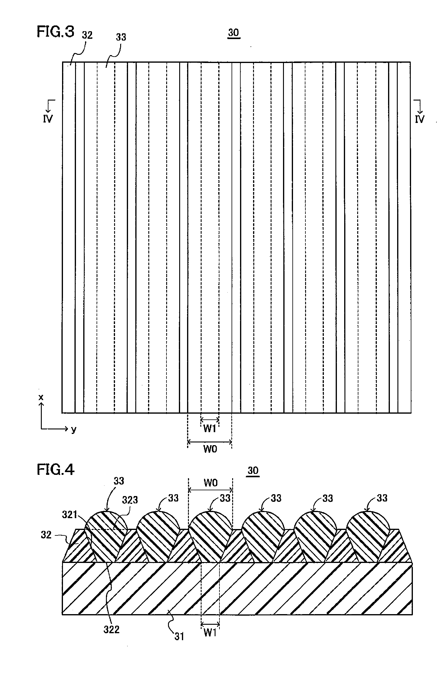
[0095]An optical sheet (lenticular lens sheet) according to Inventive Example 1 in a shape as shown in FIGS. 3 and 14 and a prism sheet according to a comparative example were produced and examined for their angular distributions of brightness.

[0096]Manufacturing Method

[0097]The optical sheet according to Inventive Example 1 was produced by the following method. To start with, a concave roll plate having a plurality of grooves arranged in the axial direction and extending in the circumferential direction was prepared. The cross sectional shape of grooves in the concave roll plate was a trapezoid, the bottom width was 10 μm, the upper width was 30 μm, the groove depth was 30 μm, and the pitch of the grooves was 50 μm.

[0098]The grooves of the thus prepared concave roll plate were filled with ultraviolet curing resin containing 40 parts by weight of titanium oxide particles. A polyethylene terephthalate (PET) film 310 as thick as 100 μm was prepared as a transparent substrate. The ultr...

second embodiment

[0109]An optical sheet (micro-lens array) according to Inventive Example 2 in a shape shown in FIGS. 12 and 16 were produced and examined for the angular distribution of brightness.

[0110]Manufacturing Method

[0111]The optical sheet according to Inventive Example 2 was produced by the following method. To start with, a PET film 510 as thick as 188 μm was prepared as a transparent substrate. Using a rotary screen plate in a rectangular mesh pattern in which the pitch was 200 μm and the line width was 120 μm, ink produced by having 75 parts by weight of titanium oxide and 25 parts by weight of acrylic resin dispersed in toluene was screen-printed on the PET film 510, and an optical reflection layer 520 having a plurality of through holes was formed.

[0112]Then, the upper surface of the optical reflection layer was provided with a fluorine-based moisture proof coating (HANARL®FZ-610C manufactured by Kanto Kasei Ltd.) 540. After being provided with the coating 540, ultraviolet curing resin...

third embodiment

[0117]Various optical sheets (lenticular lens sheets) in Table 1 having the sizes shown in FIG. 18 was produced while the height h between the top of the cylindrical lens and the lower opening of the through hole was changed and examined for their front side brightness.

TABLE 1height hEX0 = h / test No.(μm)(nr / (n − 1))137.30.72480.93500.93453.31558.71.1669.31.37801.5

[0118]With reference to Table 1, the value for EX0 was produced by the following Expression (2):

EX0=h / (nr / (n−1))  (2)

where n, the refractive index of a cylindrical lens was 1.54 (n=1.54), and r, the radius of curvature of the cylindrical surface of the cylindrical lens was 20 μm as shown in FIG. 18.

[0119]With reference to Table 1, for optical sheets Test Nos. 2 to 6, EX0 was in the range from 0.8 to 1.3 and all satisfied Expression (1). The value for EX0 for optical sheet Test No. 1 was 0.7, and the height h was less than the lower limit for Expression (1). The value for EX0 for optical sheet Test No. 7 was 1.5 and the heig...


PUM

PropertyMeasurementUnit
widthaaaaaaaaaa
refractive indexaaaaaaaaaa
radius of curvatureaaaaaaaaaa

Abstract

An optical sheet for a backlight is provided on a surface light source in the backlight. An optical reflection layer has a plurality of through grooves formed on a transparent substrate and arranged at a prescribed interval. The width of the through hole is narrowed from the upper surface opening to the lower surface opening. Each of the cylindrical lenses is filled within a corresponding through groove, and its surface is a cylindrical surface that covers the upper surface opening of the through groove. Light from the light source comes in only from the lower surface opening, so that the angle of incidence of light when the light reaches the cylindrical surface can be controlled, and an increased amount of light deflected toward the front surface can be emitted. Therefore, the optical sheet for a backlight can collect light from the surface light source in the front surface direction.

Description

TECHNICAL FIELD[0001]The present invention relates to an optical sheet for a backlight, and a backlight and a display device using the optical sheet, and more specifically to an optical sheet for a backlight that deflects light from a surface light source in the front surface direction, and a backlight and a display device using the optical sheet.BACKGROUND ART[0002]In the field of display devices such as a liquid crystal display, there is a demand for improved front side brightness. Therefore, in a backlight device for use in such a display, an optical member used to control the angular distribution of brightness and improve the front side brightness is provided. As disclosed by JP 3262230 B, a prism sheet is generally used as such an optical member.[0003]As shown in FIG. 24, the prism sheet 100 has a plurality of prisms PL arranged in parallel to one another. Diffused light R100 from a surface light source is refracted at the side plane BP0 of a prism PL and emitted as it is defle...

Claims


Application Information

Patent Timeline
Patent Type & Authority Applications(United States)
IPC IPC(8): G02F1/13357F21V13/04G09F13/04
CPCG02B3/06G02F2001/133607G02F1/133606G02F1/133604G02F1/133607G02B3/00G02B5/02G02F1/1335
Inventor YAMADA, YUKINORI
Owner HITACHT MAXELL LTD
Why Eureka
Try Eureka