
Methods and apparatus for crossing occlusions in blood vessels

a technology of blood vessel and occlusion, applied in the field of chronic total occlusion treatment, can solve the problems of significant risks to patient health, pain in angina, loss of cardiac tissue or patient death, etc., and achieve the effect of facilitating the treatment of the blood vessel

Active Publication Date: 2009-10-29
BOSTON SCI SCIMED INC
View PDF100 Cites 78 Cited by
  • Summary
  • Abstract
  • Description
  • Claims
  • Application Information

AI Technical Summary

Benefits of technology

The present invention is about a device and method for treating blood vessels. The device includes a shaft with a handle assembly fixed to the end. The handle assembly has a first portion that rotates to cause the shaft to rotate when torque is applied to the shaft below a certain level. This allows for controlled rotation of the shaft without causing excessive torque. The method involves rotating the handle assembly in a certain direction to apply torque to the shaft and cause the shaft to rotate. This device and method make it easier to treat blood vessels.

Problems solved by technology

Due to age, high cholesterol and other contributing factors, a large percentage of the population has arterial atherosclerosis that totally occludes portions of the patient's vasculature and presents significant risks to patient health.
For example, in the case of a total occlusion of a coronary artery, the result may be painful angina, loss of cardiac tissue or patient death.
In another example, complete occlusion of the femoral and / or popliteal arteries in the leg may result in limb threatening ischemia and limb amputation.
Commonly known endovascular devices and techniques are either inefficient (time consuming procedure), have a high risk of perforating a vessel (poor safety) or fail to cross the occlusion (poor efficacy).
Physicians currently have difficulty visualizing the native vessel lumen, can not accurately direct endovascular devices toward the visualized lumen, or fail to advance devices through the lesion.

Method used


Image

  • Methods and apparatus for crossing occlusions in blood vessels
  • Methods and apparatus for crossing occlusions in blood vessels
  • Methods and apparatus for crossing occlusions in blood vessels

Examples


Embodiment Construction

[0027]Reference will now be made in detail to the exemplary embodiments of the invention, examples of which are illustrated in the accompanying drawings. Wherever possible, the same reference numbers will be used throughout the drawings to refer to the same or like parts.

[0028]The following detailed description should be read with reference to the drawings in which similar elements in different drawings are numbered the same. The drawings, which are not necessarily to scale, depict illustrative embodiments and are not intended to limit the scope of the invention.

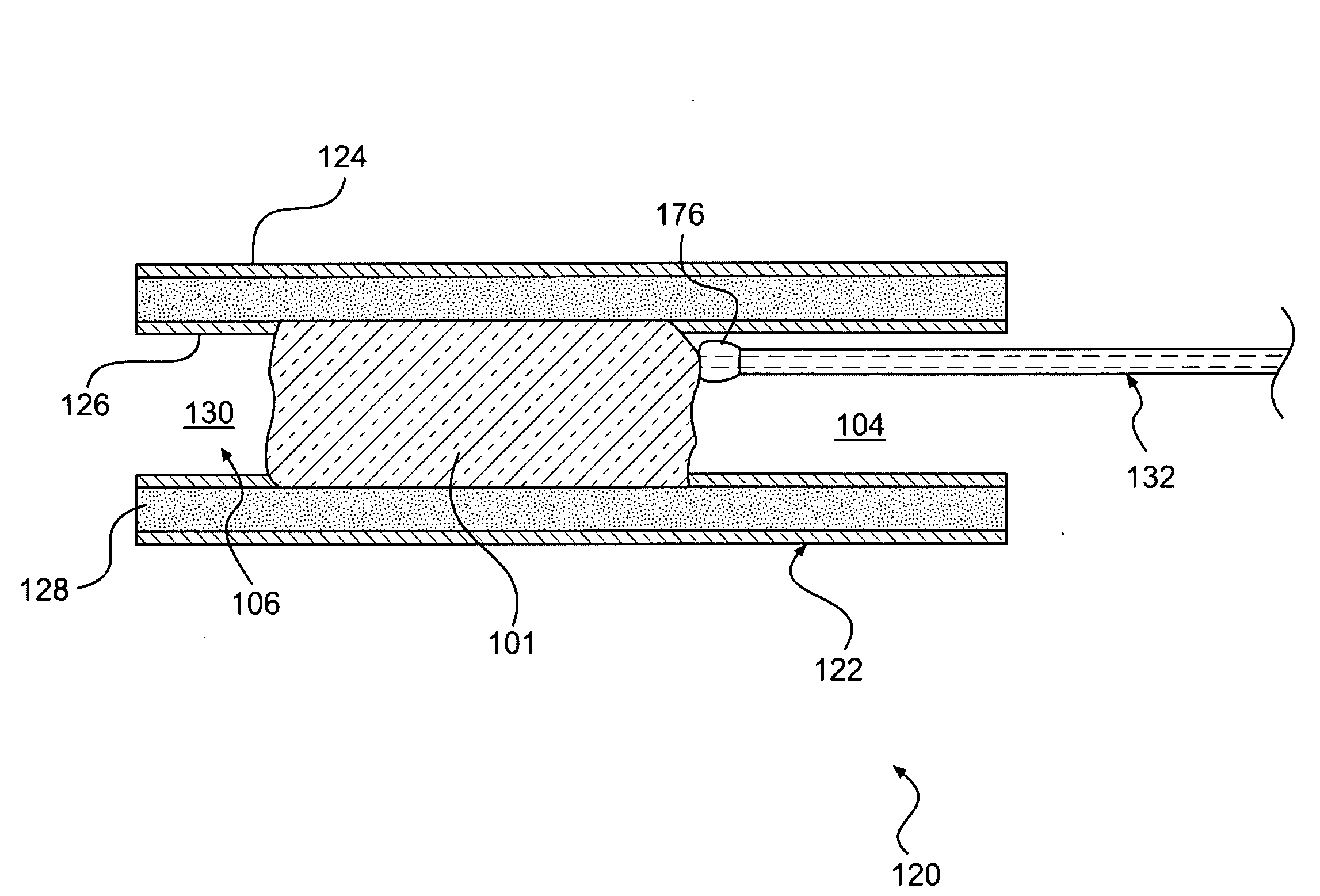
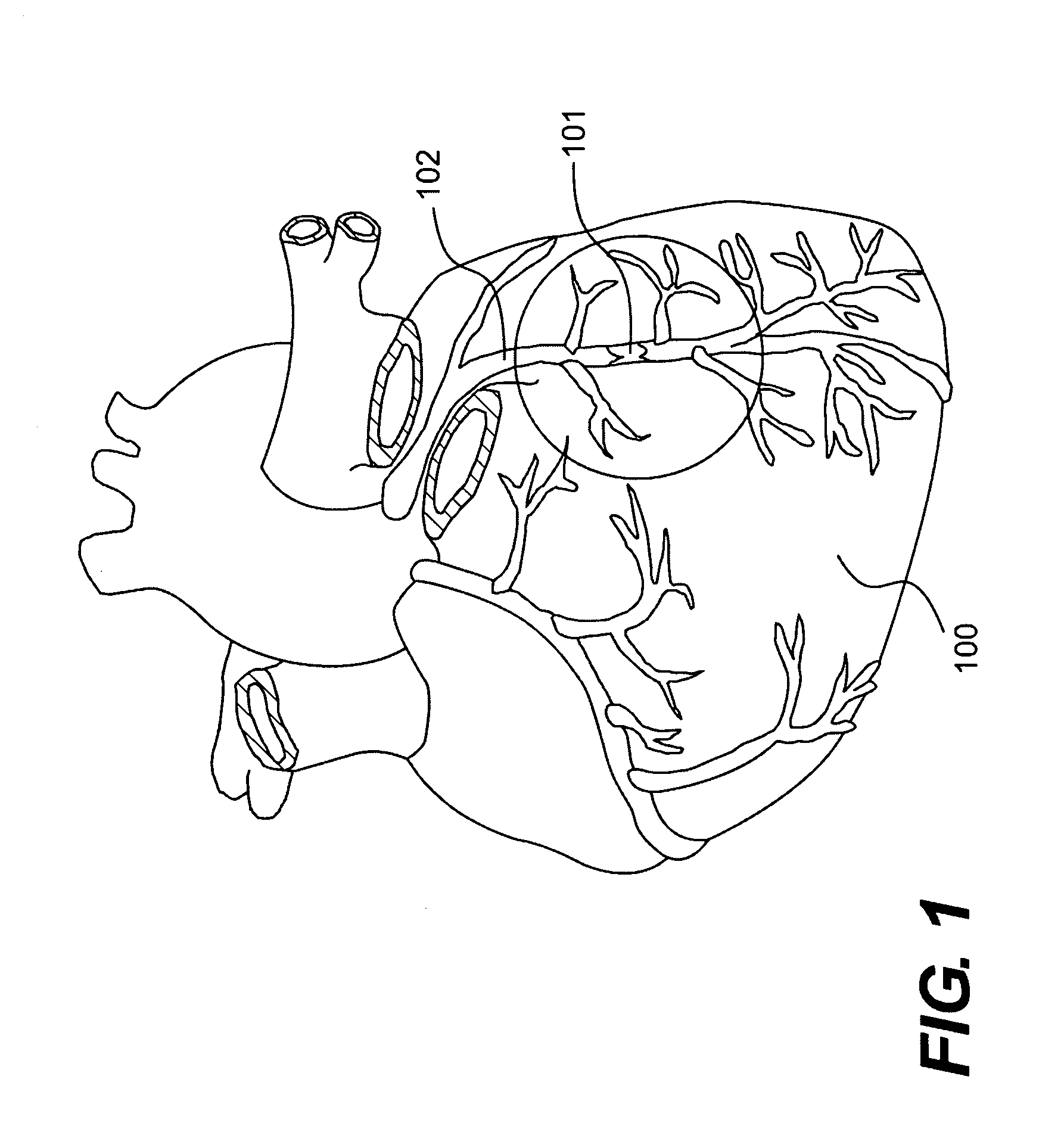
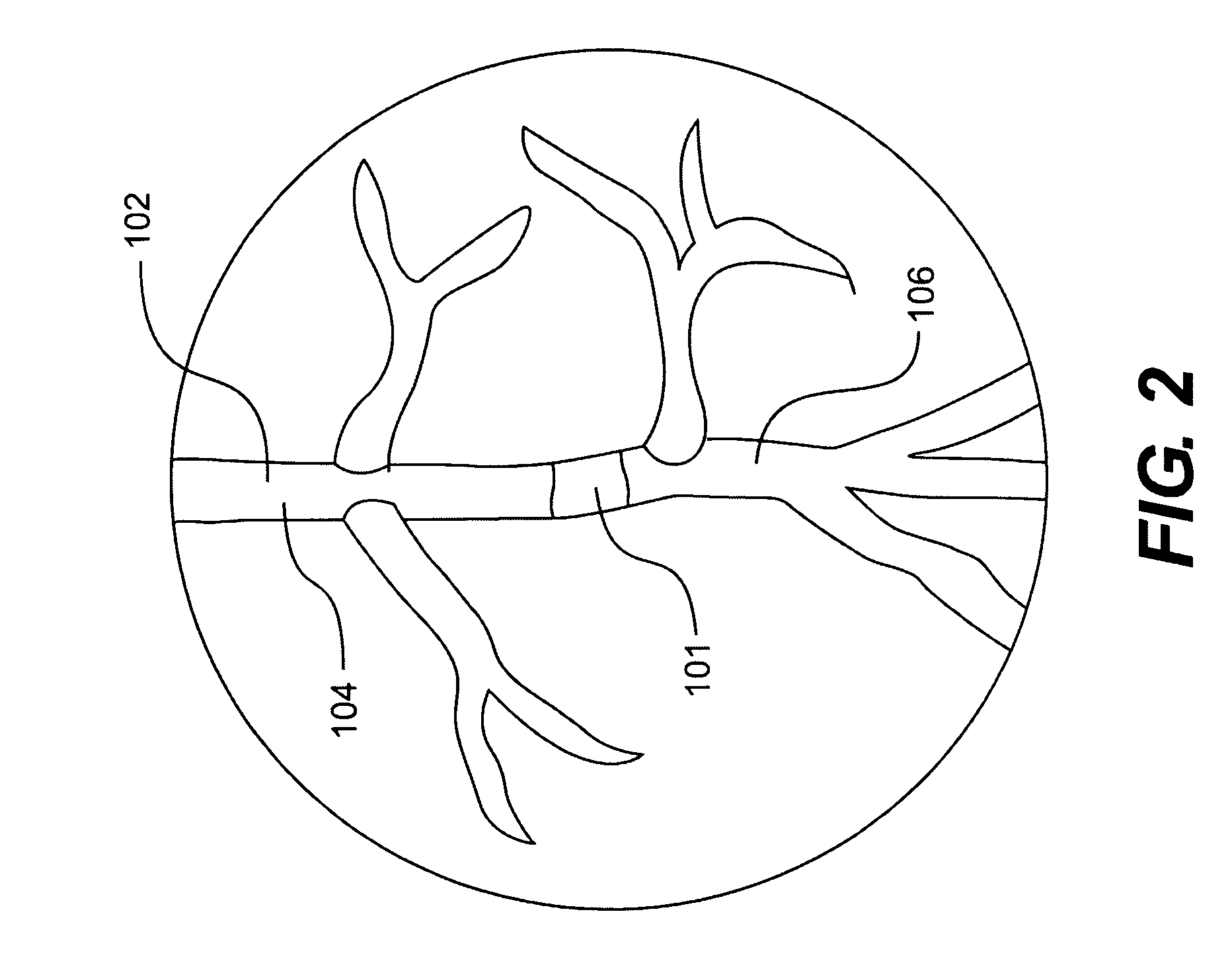
[0029]FIG. 1 is a schematic representation of a human heart 100. Heart 100 includes a plurality of coronary arteries 102, all of which are susceptible to occlusion. Under certain physiological circumstances and given sufficient time, some occlusions may become total or complete, such as total occlusion 101. As used herein, the terms total occlusion and complete occlusion are intended to refer to the same or similar degree of...


PUM


Abstract

Exemplary embodiments of the present disclosure are directed to a device for facilitating treatment via a vascular wall defining a vascular lumen containing an occlusion therein. The device includes an intravascular device including a shaft having a distal end and a proximal end. The device further includes a handle assembly fixed about the proximal end of the shaft, the handle assembly including a first portion. Further rotation of the first portion in a first direction about a longitudinal axis of the shaft causes rotation of the shaft in the first direction when a torque applied by the first portion to the shaft is below a first maximum torque. Still further, rotation of the first portion in the first direction about a longitudinal axis of the shaft does not cause rotation of the shaft in the first direction when the torque applied by the first portion to the shaft is equal to or above the first maximum torque.

Description

CROSS REFERENCE TO RELATED APPLICATION[0001]This application claims the benefit of U.S. Provisional Application No. 61 / 048,398, filed Apr. 28, 2008, which is herein incorporated by reference in its entirety.FIELD OF THE INVENTION[0002]Embodiments of the inventions described herein relate to devices and associated methods for the treatment of chronic total occlusions. More particularly, embodiments of the inventions described herein relate to devices and methods for crossing chronic total occlusions and establishing a pathway blood flow past the chronic total occlusions.BACKGROUND OF THE INVENTION[0003]Due to age, high cholesterol and other contributing factors, a large percentage of the population has arterial atherosclerosis that totally occludes portions of the patient's vasculature and presents significant risks to patient health. For example, in the case of a total occlusion of a coronary artery, the result may be painful angina, loss of cardiac tissue or patient death. In anoth...

Claims


Application Information

Patent Timeline
Patent Type & Authority Applications(United States)
IPC IPC(8): A61B17/22
CPCA61B17/32002A61B2017/00407A61B2017/22094A61B17/320758A61B2019/301A61B17/22A61B2019/2292A61B34/76A61B2090/031A61B2017/00469
Inventor ROBINSON, DAVID BRYANKUGLER, CHAD JOHNOLSON, MATTHEW JONATHANOLSON, ROSS ARLENJACOBS, PETER ALAN
Owner BOSTON SCI SCIMED INC
Learn More