Physical quantity measuring instrument and signal processing method thereof

a physical quantity and measurement instrument technology, applied in instruments, galvano-magnetic hall-effect devices, data acquisition and logging, etc., can solve the problems of increasing the noise component against the signal on the other side, the noise of portable equipment is susceptible to the noise of the other elements, and the sensor is miniaturized, so as to reduce the noise component and improve the reliability without increasing the size or cost of the circui

Active Publication Date: 2009-10-29
ASAHI KASEI ELECTRONICS CO LTD
View PDF4 Cites 25 Cited by
  • Summary
  • Abstract
  • Description
  • Claims
  • Application Information

AI Technical Summary

Benefits of technology

[0048]In addition, the signal detecting component can have different detection sensitivity to three-dimensional components X, Y and Z of the desired three-dimensional vector physical quantity, and the signal processing component can correct the difference in the detection sensitivity by linearly combining the signals.
[0063]Moreover, the second sign control step can invert sign relationships with respect to offset components included in the signals the signal detecting step detects and with respect to signals obtained by eliminating the offset components from the signals the signal detecting step detects.
[0069]According to the present invention, the physical quantity measuring instrument for detecting signals based on the desired physical quantity and for calculating the physical quantity by executing signal processing includes: the signal detecting component for detecting a plurality of signals based on the physical quantity; the signal processing component for linearly combining the signals detected by the signal detecting component in combinations varying with time; and the arithmetic processing component for calculating the physical quantity from signal data output by the signal processing component. Accordingly, it can reduce the noise component mixed in the physical quantity detecting unit or signal processing unit and improve the reliability without increasing the size or cost of the circuit.

Problems solved by technology

However, as the demand for miniaturization increases on the one hand, the miniaturization of the sensor generally presents a problem of increasing the noise component against the signal on the other.
In addition, the portable equipment is susceptible to noise from the other elements because its inside is very highly integrated.
These factors together offer an issue of noise reduction of the sensor.
However, when the magnetic concentrator has a much longer length with respect to its height, there is little effect of amplifying the magnetic flux density as to the magnetic field in the perpendicular direction.
Accordingly, the magnetic detection sensitivity in the perpendicular direction does not improve, which presents an inevitable problem in that the S / N ratio is worse than that in the direction parallel to the magnetic concentrator.
In addition, it is not easy to dispose the sensors in an IC in such a manner as to enable detection of the components in the three-axis directions.
To detect the magnetism parallel to the IC, however, it is necessary to dispose the elements in the perpendicular direction in the IC, which is not easy.
In addition, another problem arises in that the IC becomes higher by the amount of placing the elements perpendicularly to the IC.
However, the method presents a new problem of increasing the size of the magnetic sensor.
However, the foregoing Patent Documents have a problem in that since they detect the physical quantity to be measured for each component individually, the timing of measurement for each component varies from component to component.
It means, when the physical quantity to be measured or the configuration of a device is changed, the noise reduction method applied to the foregoing Patent Document 3 cannot achieve sufficient effect often.
However, it has a problem of increasing the circuit scale and current consumption.
In addition, although it has an advantage of general-purpose noise component reduction to use elements or semiconductor components that are resistant to generating noise components, the elements or components are usually expensive and large, thereby making it difficult to reduce the cost and size.

Method used


Image

  • Physical quantity measuring instrument and signal processing method thereof
  • Physical quantity measuring instrument and signal processing method thereof
  • Physical quantity measuring instrument and signal processing method thereof

Examples


embodiment 1

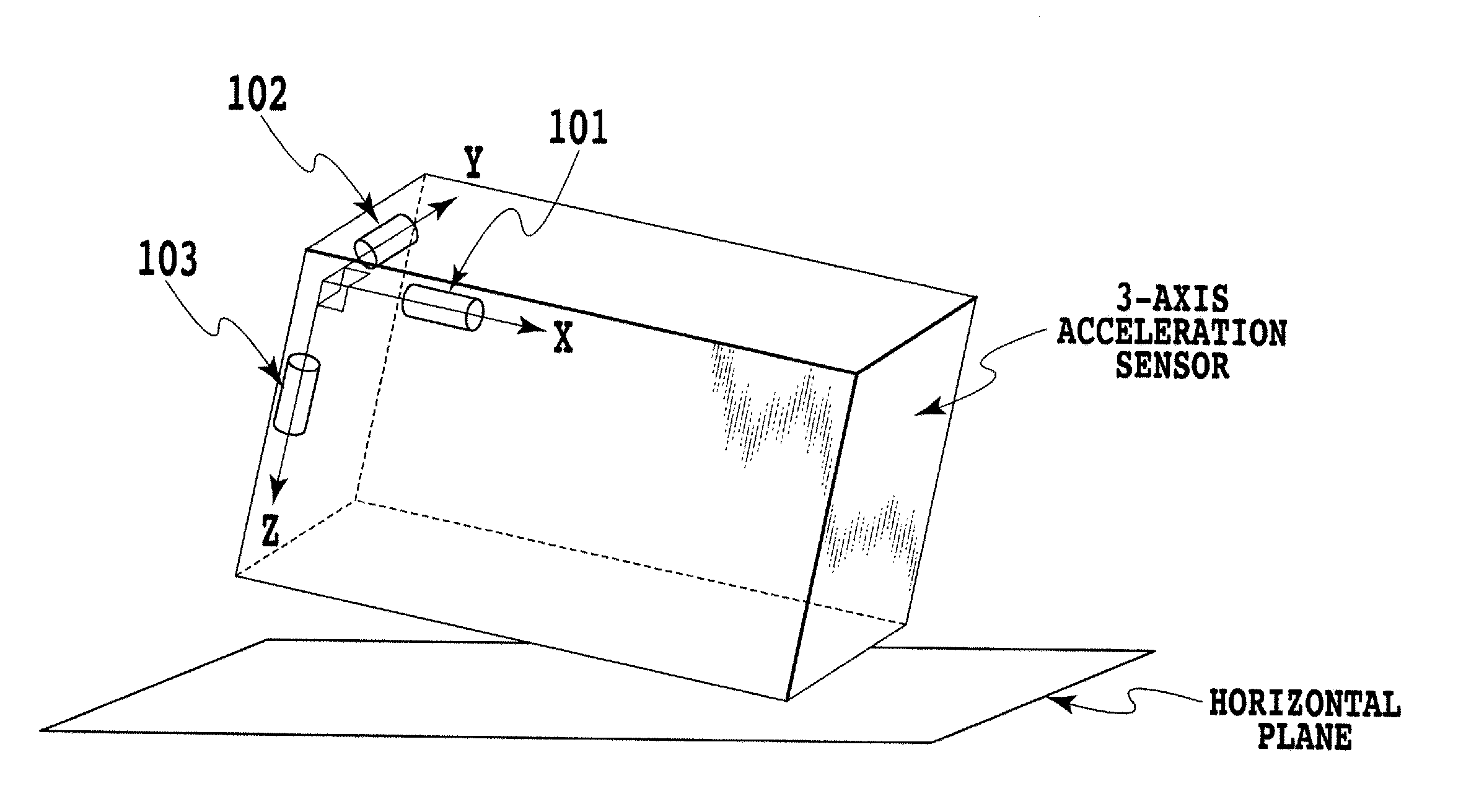
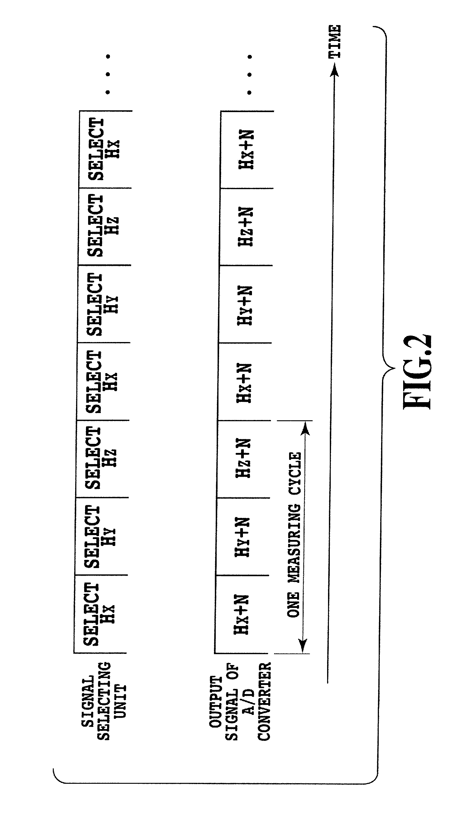
[0100]FIG. 7 is a block diagram showing a schematic configuration of a three-axis acceleration sensor, which is an embodiment 1 of the physical quantity measuring instrument in accordance with the present invention. Here, an X-axis sensor element 111, a Y-axis sensor element 112 and a Z-axis sensor element 113 correspond to the physical quantity detecting unit 11 in FIG. 6; a signal selecting unit 114, an operational amplifier 115 and an A / D converter 116 correspond to the signal processing unit 12 in FIG. 6; and an arithmetic processing unit 117 corresponds to the arithmetic processing unit 13 in FIG. 6. In addition, the reference numeral 118 designates a noise component added to the signal schematically.

[0101]As the acceleration sensor elements, Piezo-resistive sensors are suitable. However, any elements such as electrostatic capacitance sensors, piezoelectric sensors and thermal distribution detecting sensors can be used as long as they can detect acceleration.

[0102]In addition, ...

embodiment 2

[0118]FIG. 9 is a block diagram showing a schematic configuration of a magnetic sensor which is an embodiment 2 of the physical quantity measuring instrument in accordance with the present invention. FIG. 13A and FIG. 13B show a configuration example of the detecting unit of the embodiment 2 in accordance with the present invention, which has the same configuration as that of the Patent Document 2. Because of the effect of the magnetic concentrator, the sensor elements 211 and 212 can detect not only the signal based on the Z-axis component of the magnetic field, but also the signal based on the X-axis component; and the sensor elements 213 and 214 can detect not only the signal based on the Z-axis component of the magnetic field, but also the signal based on the Y-axis component simultaneously.

[0119]The magnetic concentrator consists of a ferromagnetic material, a material having a high relative permeability. In addition, the sensor elements 211-214, which have sensitivity to the m...

embodiment 3

[0143]FIG. 14A, FIG. 14B and FIG. 14C are diagrams for explaining an embodiment 3 of the physical quantity measuring instrument in accordance with the present invention: FIG. 14A is a schematic diagram of a configuration example of the detecting unit; FIG. 14B is a projection of a configuration example B of the detecting unit onto the X-Y plane; and FIG. 14C is a projection of a configuration example C of the detecting unit onto the X-Z plane.

[0144]The configuration example B shown in FIG. 14B has the sensor elements 211-214 disposed over the X-Y plane and inclined in the Z-axis direction each at an angle θ with respect to the X-Y plane.

[0145]Unless the sensor elements 211-214 have inclination in the Z-axis direction, they detect only the components corresponding to the axes along which they are disposed such as the sensor elements 211 and 212 detect the signal based on the X-axis component of the magnetic field, and the sensor elements 213 and 214 detect the signal based on the Y-a...


PUM


Abstract

The present invention relates to a physical quantity measuring instrument and signal processing method thereof capable of reducing noise components and improving reliability without increasing size or cost of the circuit. A physical quantity detecting unit (11) has signal detecting components for detecting a plurality of signals based on a desired physical quantity and detects the desired physical quantity. A signal processing unit (12) executes signal processing of the signals detected on the individual detecting axes by the physical quantity detecting unit (11) for linearly combining the signals in different combinations with time. An arithmetic processing unit (13) combines and calculates a plurality of signals based on the physical quantity associated with the physical quantity detecting unit (11) from the signal data output by the signal processing unit (12). It can linearly combine the signals from the plurality of detecting axes in different combinations with time, output them, and obtain desired signal components whose noise components are reduced by calculating the outputs.

Description

TECHNICAL FIELD[0001]The present invention relates to a physical quantity measuring instrument and a signal processing method thereof, and more particularly to a physical quantity measuring instrument and a signal processing method thereof relating to noise reduction in physical quantity measurement with a plurality of sensor elements.BACKGROUND ART[0002]In recent years, there has been an increasing trend for portable equipment to incorporate a multiaxial physical quantity measuring instrument such as a three-axis acceleration sensor or three-axis magnetic sensor.[0003]FIG. 1 is a block diagram showing a schematic configuration of a three-axis acceleration sensor as a conventional physical quantity measuring instrument, which block diagram corresponds to FIG. 5 shown in Patent Document 1. Three acceleration sensor elements 101, 102 and 103 detect a three-dimensional acceleration vector, and signals Hx, Hy and Hz corresponding to the X-axis component, Y-axis component and Z-axis comp...

Claims


Application Information

Patent Timeline
Patent Type & Authority Applications(United States)
IPC IPC(8): G06F15/00G01P15/00G01D3/028G01D3/036G01P15/18G01R33/02G01R33/07H01L43/06
CPCG01D3/028G01D3/036G01R33/07G01R33/0206G01P15/18G01P15/00G01P15/105
Inventor YAMASHITA, MASAYAKITAMURA, TORUKITAURA, MUNEHIRO
Owner ASAHI KASEI ELECTRONICS CO LTD
Why Eureka
Try Eureka