Eureka AIR delivers breakthrough ideas for toughest innovation challenges, trusted by R&D personnel around the world.

Method for pretreating electrochemical capacitor negative electrode, method for manufacturing the electrochemical capacitor negative electorde, and method for manufacturing electrochemical capacitor using the method for manufacturing the electrochemical capacitor negative electrode

Active Publication Date: 2009-11-05
PANASONIC CORP
View PDF9 Cites 3 Cited by
  • Summary
  • Abstract
  • Description
  • Claims
  • Application Information

AI Technical Summary

Benefits of technology

[0023]As mentioned above, in the method for pretreating the negative electrode of the electrochemical capacitor in accordance with the present invention, a lithium layer is formed on the surface of the electrode layer of the negative electrode by decal transferring. With this method, the electrode layer including the carbon material is in a state in which it immediately absorbs lithium ions before the negative electrode is combined with a positive electrode. Therefore, it is not necessary to provide a post-process for allowing the negative electrode to absorb lithium ions, thus improving productivity. Furthermore, a state in which lithium ions are absorbed by the electrode layer of the negative electrode is stabilized. Thus, an electrochemical capacitor having an excellent performance can be produced stably.

Problems solved by technology

However, an operation for allowing a carbon material to absorb lithium ions by a chemical or electrochemical method in advance is complicated, and much man-hour or cost is required.
Furthermore, it is difficult to obtain an excellent performance stably.
However, a lithium ion battery has a higher resistance and remarkably short lifetime by a charge and discharge cycle in a large current as compared with an electric double layer capacitor.

Method used


Image

  • Method for pretreating electrochemical capacitor negative electrode, method for manufacturing the electrochemical capacitor negative electorde, and method for manufacturing electrochemical capacitor using the method for manufacturing the electrochemical capacitor negative electrode
  • Method for pretreating electrochemical capacitor negative electrode, method for manufacturing the electrochemical capacitor negative electorde, and method for manufacturing electrochemical capacitor using the method for manufacturing the electrochemical capacitor negative electrode
  • Method for pretreating electrochemical capacitor negative electrode, method for manufacturing the electrochemical capacitor negative electorde, and method for manufacturing electrochemical capacitor using the method for manufacturing the electrochemical capacitor negative electrode

Examples


Embodiment Construction

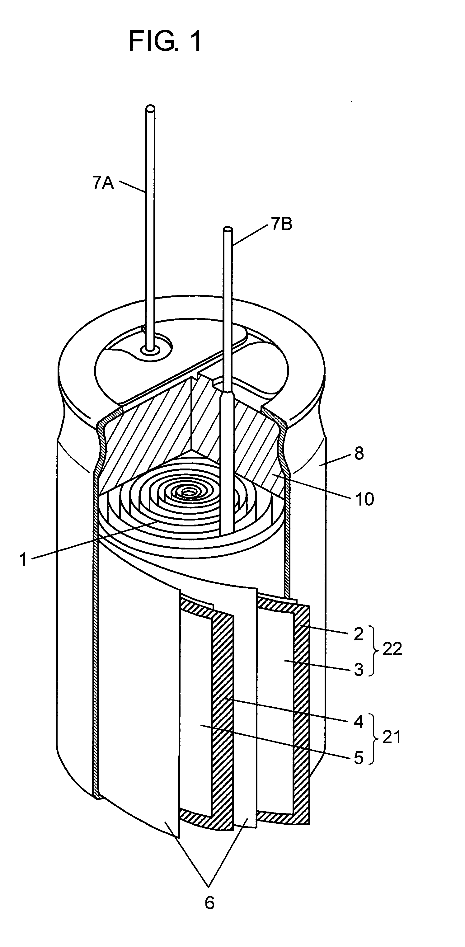
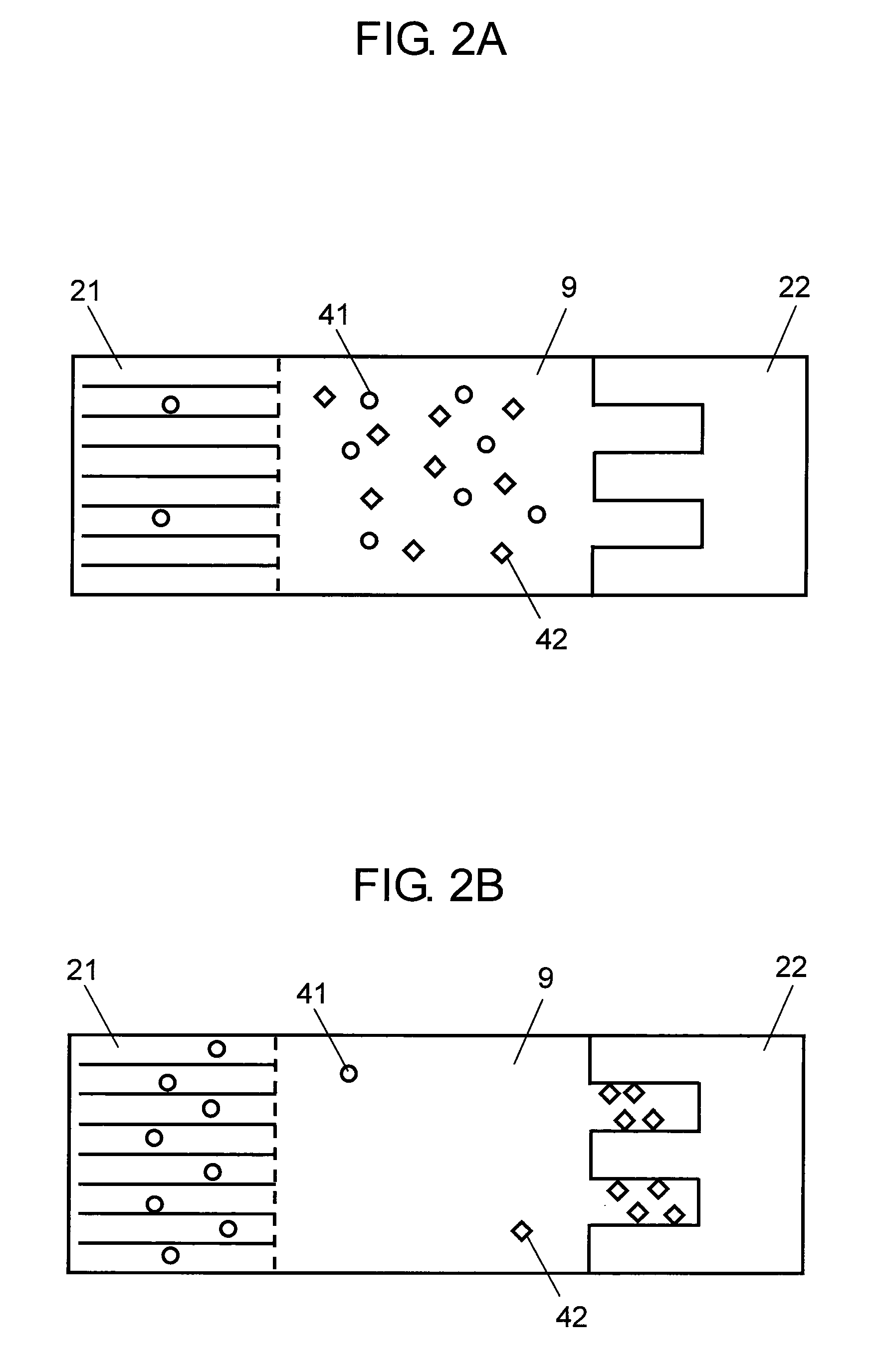
[0030]FIG. 1 is a partially cut-away perspective view showing a configuration of an electrochemical capacitor in accordance with an exemplary embodiment of the present invention. FIGS. 2A and 2B are conceptual diagrams showing a state in which the electrochemical capacitor is discharged and charged, respectively. This electrochemical capacitor includes element 1, case 8, sealing rubber 10 and electrolyte solution 9.

[0031]Element 1 includes negative electrode 21, positive electrode 22 and separator 6. Separator 6 is disposed between negative electrode 21 and positive electrode 22 and prevents negative electrode 21 and positive electrode 22 from being brought into contact with each other.

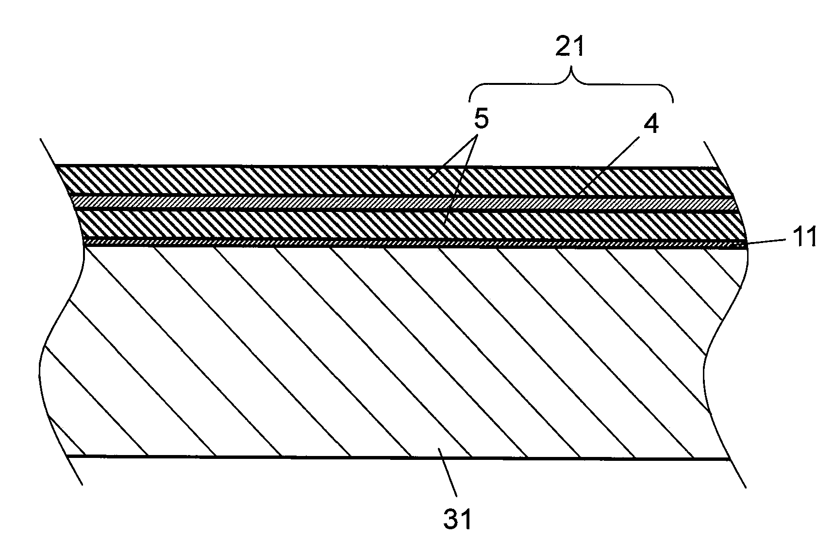
[0032]Negative electrode 21 includes current collector 4 as a first current collector that does not react with lithium, and electrode layers 5 formed on both surfaces of current collector 4. Current collector 4 is, for example, a copper foil. Electrode layer 5 includes a carbon material capable of rev...


PUM

PropertyMeasurementUnit
Temperatureaaaaaaaaaa

Abstract

A negative electrode of an electrochemical capacitor includes an electrode layer using a material capable of reversibly absorbing and releasing a lithium ion. A method for pretreating the negative electrode includes forming a lithium layer on a substrate by a gas phase method or a liquid phase method, and transferring the lithium layer onto a surface of the electrode layer of the negative electrode.

Description

[0001]This application is a U.S. national phase application of PCT international application PCT / JP2007 / 063803.TECHNICAL FIELD[0002]The present invention relates to a method for manufacturing an electrochemical capacitor used for various electronic equipment, a backup power source, regeneration of hybrid cars, fuel cell cars, electric power storage, or the like. More particularly, it relates to a method for pretreating such a negative electrode of an electrochemical capacitor and a method for manufacturing such a negative electrode.BACKGROUND ART[0003]An electric double layer capacitor has a high withstand voltage, a large capacitance, and a high reliability with respect to rapid charge and discharge. Therefore, it is used in many fields. For positive and negative electrodes of a general electric double layer capacitor, a polarizable electrode mainly including activated carbon is used. Furthermore, the withstand voltage of an electric double layer capacitor is 1.2 V when an aqueous ...

Claims


Application Information

Patent Timeline
IPC IPC(8): H01G9/058H01G9/042H01G9/00H01G11/06H01G11/22H01G11/24H01G11/30H01G11/32H01G11/38H01G11/42H01G11/44H01G11/62H01G11/68H01G11/70H01G11/86H01M4/02H01M4/1393H01M10/0585H01M10/0587
CPCH01G9/0029H01M4/04H01M4/13H01M10/052Y10T29/417Y02T10/7011Y02T10/7022H01G11/50Y02E60/13Y02E60/122Y02E60/10Y02T10/70Y02P70/50
Inventor KONDOU, KEIICHINOMOTO, SUSUMUSHIMAMOTO, HIDEKI
Owner PANASONIC CORP
Why Eureka
Eureka Blog
Learn More