Integrating sphere photovoltaic receiver (powersphere) for laser light to electric power conversion

a photovoltaic receiver and laser light technology, applied in the field of laser power beaming and photovoltaic cells, can solve the problems of increasing the temperature of the solar cell, wasting the remainder of available energy outside of their limited spectral response, and reducing the efficiency of the solar cell

Inactive Publication Date: 2009-11-05
ORTABASI UGUR
View PDF22 Cites 105 Cited by
  • Summary
  • Abstract
  • Description
  • Claims
  • Application Information

AI Technical Summary

Problems solved by technology

State-of-the-art single junction solar arrays as well as concentrators using single junction solar cells utilize only a limited portion of the available solar spectrum, thereby wasting the remainder of available energy outside of their limited spectral response.
The limitation is caused mainly by two basic “photon loss” mechanisms within the cells, namely, (1) loss by longer wavelengths and (2) loss by excess energy of photons.
The excess energy raises the temperature of the solar cell and degrades its performance.
Thus, even high quality cells with excellent quantum efficiencies, such as GaAs, exhibit relatively modest conversion efficiencies since they cannot respond to more than a relatively small portion of the incident spectrum.
Under actual operating conditions, the MJ concentrator system performance can drop more than 12 to 15% (absolute) against the bare cell performance and defeat the use of high efficiency MJ cells.
Some of the major concentration-related performance losses in MJ cells are caused by the following shortcomings: absorption of light in the top cells, chromatic aberrations caused by the concentrator optics, flux non-uniformity on the cells, limited heat removal from the top cells, current limitation in the cells, series resistance, shadowing losses due to finger contacts on the cells, and limited acceptance angle for photon incidence on the cells.
MJ cells, however, are more vulnerable to most of these performance-limiting factors.
The relative deterioration of MJ cells becomes worse as the n...

Method used


Image

  • Integrating sphere photovoltaic receiver (powersphere) for laser light to electric power conversion
  • Integrating sphere photovoltaic receiver (powersphere) for laser light to electric power conversion
  • Integrating sphere photovoltaic receiver (powersphere) for laser light to electric power conversion

Examples


Embodiment Construction

[0033]Reference is now made in detail to a specific embodiment of the present invention, which illustrates the best mode presently contemplated by the inventor for practicing the invention. Alternative embodiments are also briefly described as applicable.

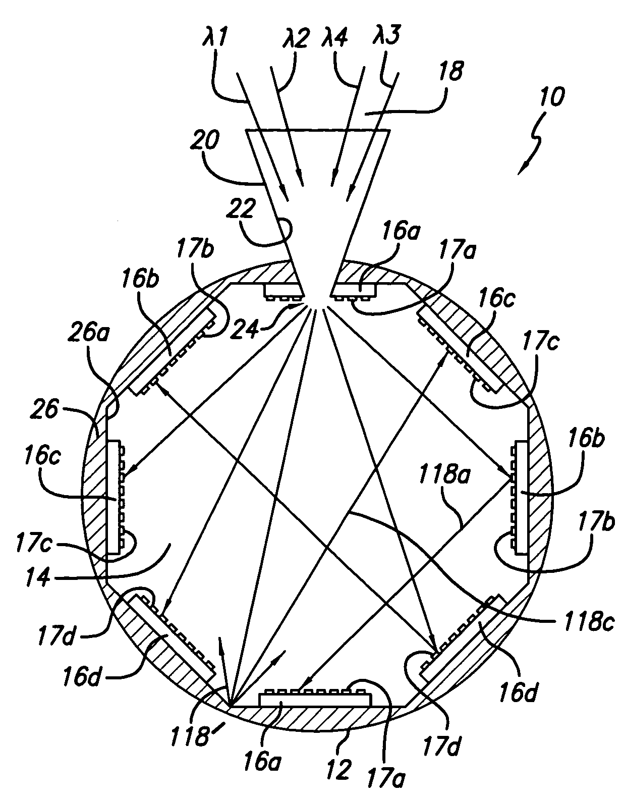
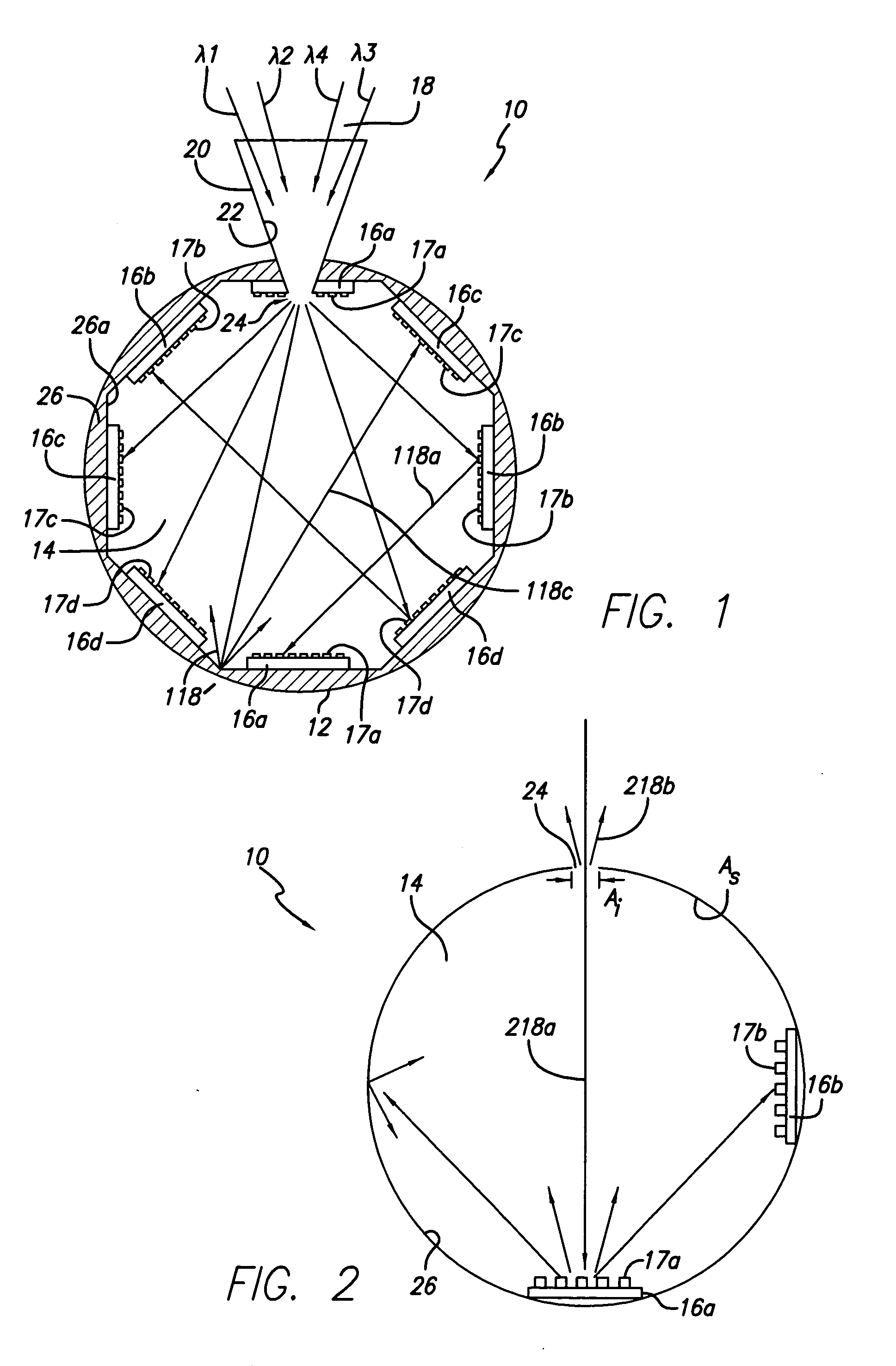
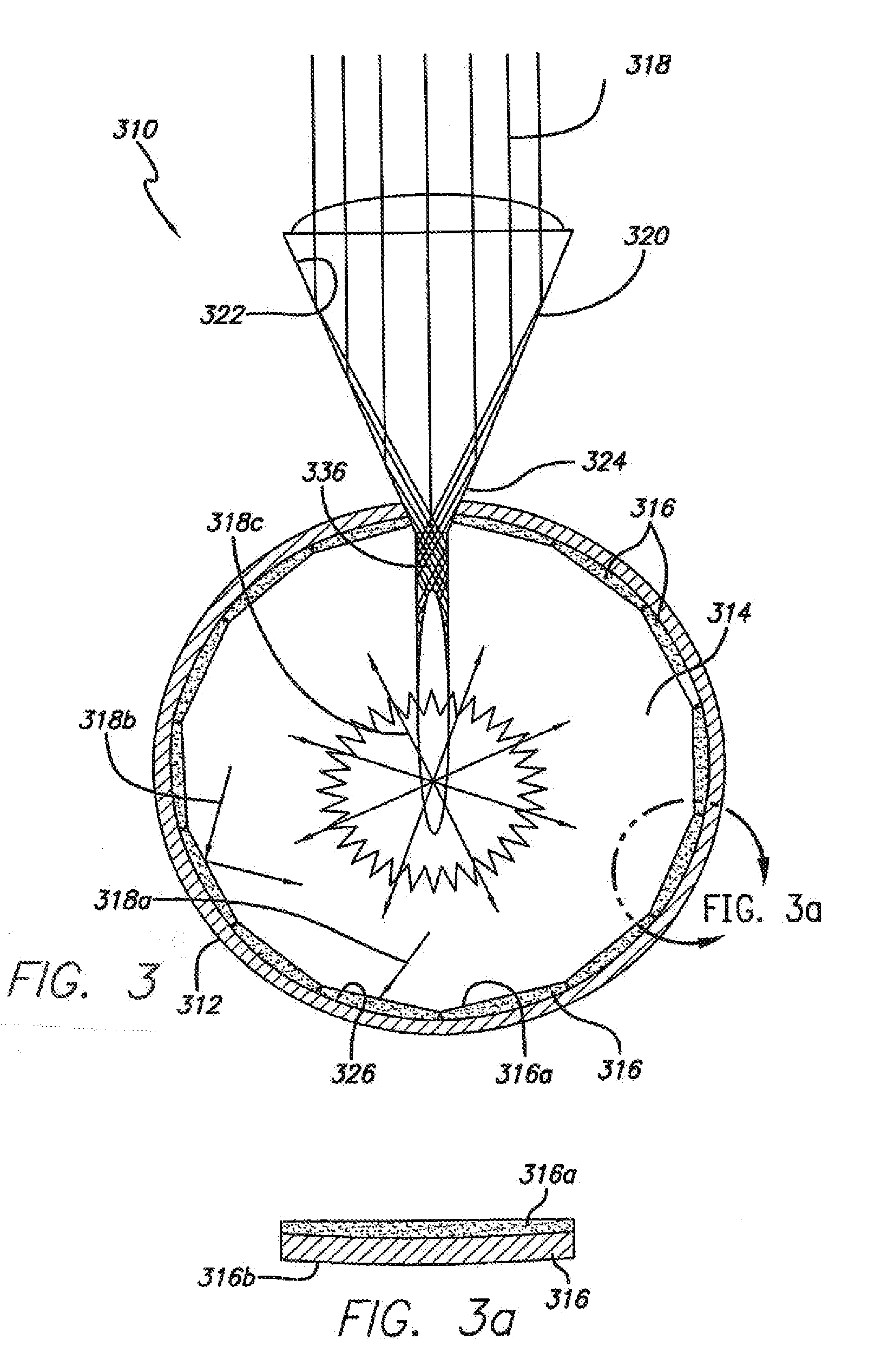
[0034]The embodiments herein are directed to an integrating sphere photovoltaic (PV) receiver, or module, for converting laser light into electric power. The receiver is called a “PowerSphere”.

[0035]The basic concept of the PowerSphere is based on a photovoltaic cavity converter (PVCC) module that has been designed for a concentration in the range of 500 to over 1000 suns and a power output range of a few kilowatts to 50 kWe when combined with a primary dish and a secondary concentrator. That PVCC module is disclosed and claimed in the above-identified parent application, now U.S. Pat. No. ______. The PVCC module herein is expected to find use in, for example, DOE's Concentrating Solar Power (CSP) program to develop systems in the 1...


PUM


Abstract

A photovoltaic module for converting laser radiation from a laser emitting light at a wavelength to electrical power is provided. The module comprises: (a) a housing having a cavity of generally optimized closed shape inside the housing, the cavity having an internal surface area As and including an opening for admitting the laser radiation into the cavity, the opening having an entrance aperture area Ai that is substantially smaller than As; and (b) a plurality of photovoltaic cells within the cavity, the photovoltaic cells having an energy bandgap to respond to the wavelength and generate the electrical power.

Description

CROSS-REFERENCE TO RELATED APPLICATION[0001]The present application is a continuation-in-part application of Ser. No. 10 / 151,640, filed May 17, 2002, and recently allowed, the contents of which are incorporated herein by reference.TECHNICAL FIELD[0002]The present invention is related generally to laser power beaming, employing photovoltaic cells, and, more particularly, to a novel photovoltaic module for converting a directed laser beam into electrical power.BACKGROUND ART[0003]State-of-the-art single junction solar arrays as well as concentrators using single junction solar cells utilize only a limited portion of the available solar spectrum, thereby wasting the remainder of available energy outside of their limited spectral response. The limitation is caused mainly by two basic “photon loss” mechanisms within the cells, namely, (1) loss by longer wavelengths and (2) loss by excess energy of photons. In the former case, photons with energy smaller than the “energy bandgap” or “forb...

Claims


Application Information

Patent Timeline
IPC IPC(8): H01L31/055
CPCY02E10/52H01L31/0547H01L31/0543H01L31/0549
Inventor ORTABASI, UGUR
Owner ORTABASI UGUR
Why Eureka
Try Eureka