Solar concentrator

a concentrator and solar energy technology, applied in the direction of photovoltaics, electrical equipment, semiconductor devices, etc., can solve the problems of difficult to find suitable fluorescent dyes as absorbing materials, difficult to find fluorescent dyes that are effective in diffuse light, and high production costs of their manufacture materials, etc., to achieve efficient and effective concentrating incident radiation, low surface area, and minimal amount of self-absorption

Inactive Publication Date: 2009-11-05
EASTMAN KODAK CO
View PDF8 Cites 15 Cited by
  • Summary
  • Abstract
  • Description
  • Claims
  • Application Information

AI Technical Summary

Benefits of technology

[0034]The radiation concentrator according to the invention is capable of efficiently and effectively concentrating incident radiation upon a large surface area of the concentrator to radiation output (e.g. to a photovoltaic device) of relatively low surface area (e.g. an edge of a sheet). The concentrator by having embedded therein a phosphorescent dye (or dye system comprising a phosphorescent dye) capable of absorbing radiation corresponding

Problems solved by technology

Many PV cells, however, require for their manufacture materials that are expensive and energy-intensive in producing.
These have the disadvantage that they are required to track the direction of incident radiation for efficient concentration and also are not very effective in diffuse light (e.g. cloudy weather).
There are, however, several problems with this form of absorptive-emissive radiation concentrator, associated with the difficulty in finding suitable fluorescent dyes as absorbing materials.
Typical organic fluorescent dyes having broad band absorption and emission have absorption-emission spectra which have significant levels of overlap, which results in re-absorption of emitted radiation.
However, the disadvantages with this method are that the edge-mounted PV element is required to be three times the size (to cover three edges) and it is difficult to identify appropriate fluorescent dyes that absorb at different wavelengths but emit at the same narrow wavelength suitable for the PV element whilst meeting the ot

Method used


Image

  • Solar concentrator
  • Solar concentrator
  • Solar concentrator

Examples


example 1

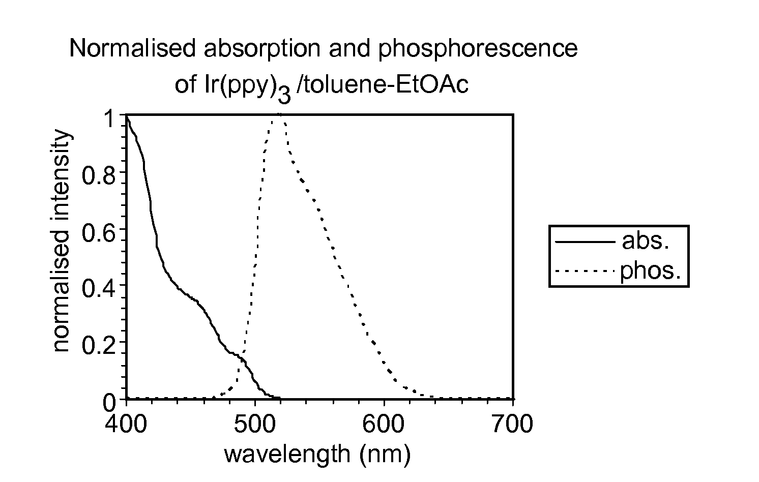
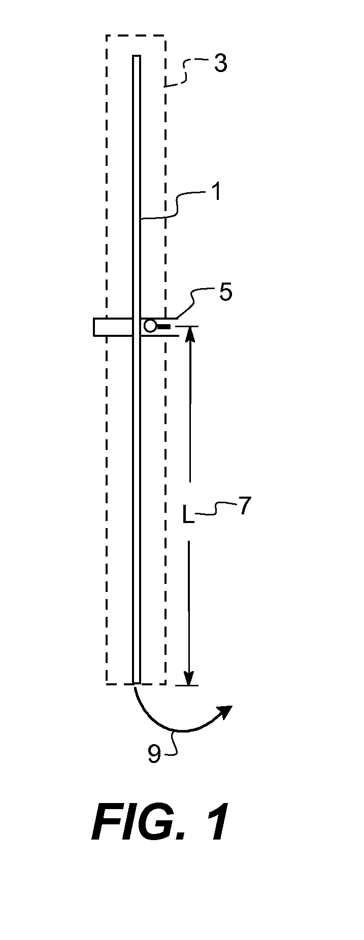
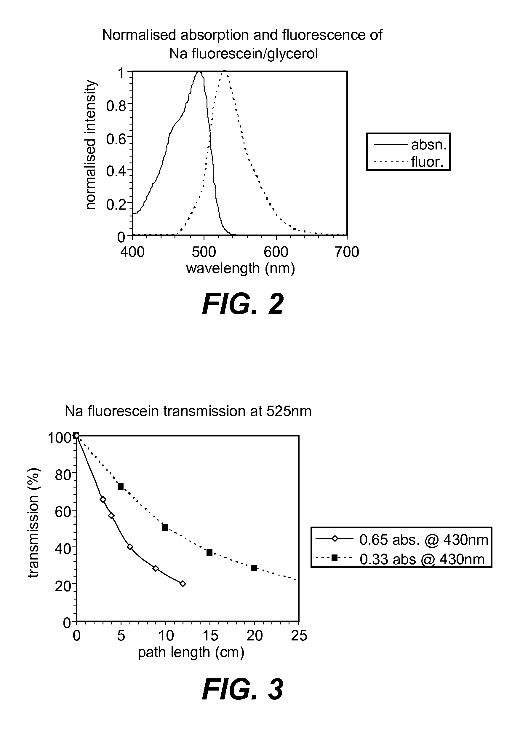
[0103]Two samples, one involving a conventional high quantum yield fluorescent dye, and one involving a high quantum yield phosphorescent dye belonging to the class claimed, were prepared to demonstrate the 1-dimensional efficiency of luminescence transmission. Glass tubes (45 cm length, 0.40 cm outer diameter, 0.24 cm. inner diameter, glass refractive index 1.47) were filled with individual dye solutions, which were prepared from a solvent or solvent mixture, whose refractive index was matched to that of the glass tube. The dye solutions under comparison were chosen to have nearly identical emission profiles with full-width half-maximum positions at approximately 500 nm and 560 nm. Solutions were excited by a 430 nm LED (3 mm diam.) at different positions along the tube, the different solutions under comparison were prepared to have the same absorbance at this excitation wavelength. The arrangement was as shown in FIG. 1, which shows a glass tube 1 filled with a dye solution surrou...


PUM


Abstract

A radiation concentrator suitable for use in concentrating solar radiation for efficient and low cost solar photovoltaic use, especially for example in window-mounted devices, has a radiation-transmissive element for receiving incident radiation and includes a radiation-absorbing material for absorbing incident radiation and emitting emissive radiation, a radiation output for transmitting concentrated emissive radiation, the transmissive element acting as a wave-guide for guiding the emissive radiation to the radiation output. The concentrator is characterized by the radiation-absorbing material comprising one or more photoluminescent dyes capable of phosphorescence which exhibit a high quantum yield of phosphorescent emission that is spectrally shifted from the material's absorption.

Description

FIELD OF THE INVENTION[0001]The present invention relates to the field of radiation concentration, especially solar concentration, by which radiation striking a surface can be effectively concentrated to a more intense, concentrated or higher energy form. More particularly, the invention relates to a radiation concentrator, especially a solar radiation concentrator, a material for use in a radiation concentrator, a method of concentrating incident radiation and to a method of making a radiation concentrator.BACKGROUND OF THE INVENTION[0002]Radiation concentration is finding increasing relevance for the purpose of improving the efficiency of photovoltaic (PV) cells used for power generation by improving the intensity or concentration of incident solar radiation on the cells. Photovoltaic cells are a means for converting incident radiation, typically actinic radiation such as solar radiation, into electrical energy and is considered a major component of renewable energy systems.[0003]...

Claims


Application Information

Patent Timeline
IPC IPC(8): H01L31/055
CPCY02E10/52H01L31/055
Inventor WINSCOM, CHRISTOPHER J.
Owner EASTMAN KODAK CO
Why Eureka
Try Eureka