Non-glass photovoltaic module and methods for manufacture

a photovoltaic module and non-glass technology, applied in the field of photovoltaic modules, can solve the problems of not being able to bend or cut glass plates to size, the use of glass plates presents many inherent problems, and the source of becoming a viable alternative, so as to prevent bending and cracking and prevent leakage of electrical curren

Inactive Publication Date: 2009-11-05
CHEUNG OSBERT HAY
View PDF3 Cites 53 Cited by
  • Summary
  • Abstract
  • Description
  • Claims
  • Application Information

AI Technical Summary

Benefits of technology

[0015]In yet another aspect, a photovoltaic module is provided including a support layer for imparting rigidity to the module to prevent bending and cracking.
[...

Problems solved by technology

With regard to hydroelectric power generation, while considered an environmentally friendly method for producing electrical power, geographical limitations and cost prohibit this source from becoming a viable alternative for the purposes mentioned above.
While glass is rigid and impermeable to moisture, therefore making it ideal as a structural support and weather covering for the solar cells, the use of glass plates present many inherent problems.
Most notably, glass plates cannot be bent or cut to size, and with regard to tempered glass employed for its strength, it is also heavy and expensive if the glass is to be cut to different sizes for small quantity applications.
These arrangements not only increase cost, but also add weight that must be reinforced accordingly.
In addition to weight, the application of glass-type photovoltaic elements tends to be limited by the method of manufacture of the elements.
Producing variable sizes of tempered glass is both costly and time consuming, and is one of the main challenges faced in the photovoltaic industry.
Another limitation to glass is that its fragile nature prevents it from being utilized with motion or as part of a moving body, such as with vehicles, marine vessels, and portable electrical equipment.
A problem with the high temperature method is that the reinforced material must be tolerant to the high temperature during the adhering process.
Beca...

Method used


Image

  • Non-glass photovoltaic module and methods for manufacture
  • Non-glass photovoltaic module and methods for manufacture
  • Non-glass photovoltaic module and methods for manufacture

Examples


experiment # 1

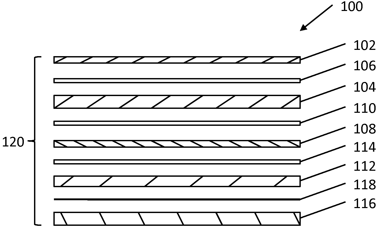
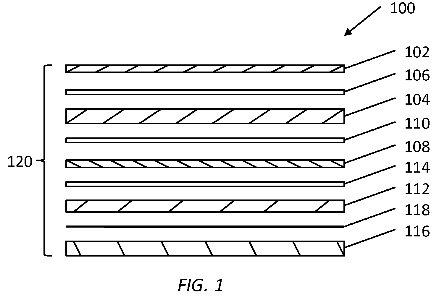
[0043]Experiment #1. The lamination of a 140 W solar panel having a panel size of approximately 42″×39″ was performed. ETFE film (5 mil) was laid out on a flat surface. A first layer of XUS film (15 mil) was applied on top of the ETFE film. Several strings cells were then laid on top of the XUS film. A second layer of XUS film was applied on top of the solar strings followed by an EPE (10 mil) layer, or a back protection sheet. The third layer of XUS film was applied on top of the back protection sheet. The substrate support panel was added last. The stacked layers of plastics, solar cells and substrate panel were placed into a laminator and underwent a lamination process at about 150 degrees C. for approximately 5 minutes and under 1 atmosphere of pressure (14.7 psi). The compressed solar panel was removed from the laminator after 5 minutes.

experiment # 2

[0044]Experiment #2. The lamination of 90 W solar panels having a panel size of approximately 21.5″×47″ was performed. ETFE film (5 mil) was laid out on a flat surface. A first layer of XUS film (15 mil) was applied on top of the ETFE film. Several strings cells were then laid on top of the XUS film. A second layer of XUS film was applied on top of the solar strings followed by an EPE (10 mil) layer, or a back protection sheet. The third layer of XUS film was applied on top of the back protection sheet. A steel sheet (10 mil) was placed on top of the XUS film. The stacked layers of plastics, solar cells and steel sheet were placed into a laminator and underwent a lamination process at about 150 degrees C. for approximately 5 minutes and under 1 atmosphere pressure (14.7 psi). The compressed solar panel was removed from the laminator after 5 minutes.


PUM


Abstract

A non-glass photovoltaic module including a non-glass cover layer, a photovoltaic layer, a back protection sheet layer, and a support layer, wherein the layers are adhesively bonded together to form a lamination.

Description

CROSS-REFERENCE TO RELATED APPLICATIONS[0001]This application claims priority to U.S. Provisional Application No. 61 / 126,541 filed May 5, 2008, and entitled “NON GLASS PHOTOVOLTAIC MODULE AND METHODS OF MAKING,” the contents of which are hereby incorporated by reference.FIELD OF THE INVENTION[0002]The present invention relates to a photovoltaic module including a non-glass protective layer and methods for manufacture of the module.BACKGROUND OF THE INVENTION[0003]Photovoltaic technology is considered to be a promising, clean energy source due to the utilization of the unlimited amount solar energy available without the harmful byproducts associated with nuclear energy and the combustion of fossil fuels and coal. In recent years, photovoltaic devices in the form of solar cells have become increasingly popular for supplying limited electrical power for domestic use and electrical equipment in remote or mobile locations where conventional sources of electricity are not readily availabl...

Claims


Application Information

Patent Timeline
IPC IPC(8): H01L31/048H01L31/18
CPCY02E10/50H01L31/048
Inventor CHEUNG, OSBERT HAY
Owner CHEUNG OSBERT HAY
Why Eureka
Try Eureka