
Clad Composite Stent

a composite stent and stent body technology, applied in the field of body implantable medical devices, can solve the problems of poor fatigue resistance, lack of elasticity of the stent, and inability to adapt to fluoroscopic imaging, so as to remove strain hardening and other stresses

Inactive Publication Date: 2009-11-05
BOSTON SCI SCIMED INC
View PDF100 Cites 25 Cited by
  • Summary
  • Abstract
  • Description
  • Claims
  • Application Information

AI Technical Summary

Benefits of technology

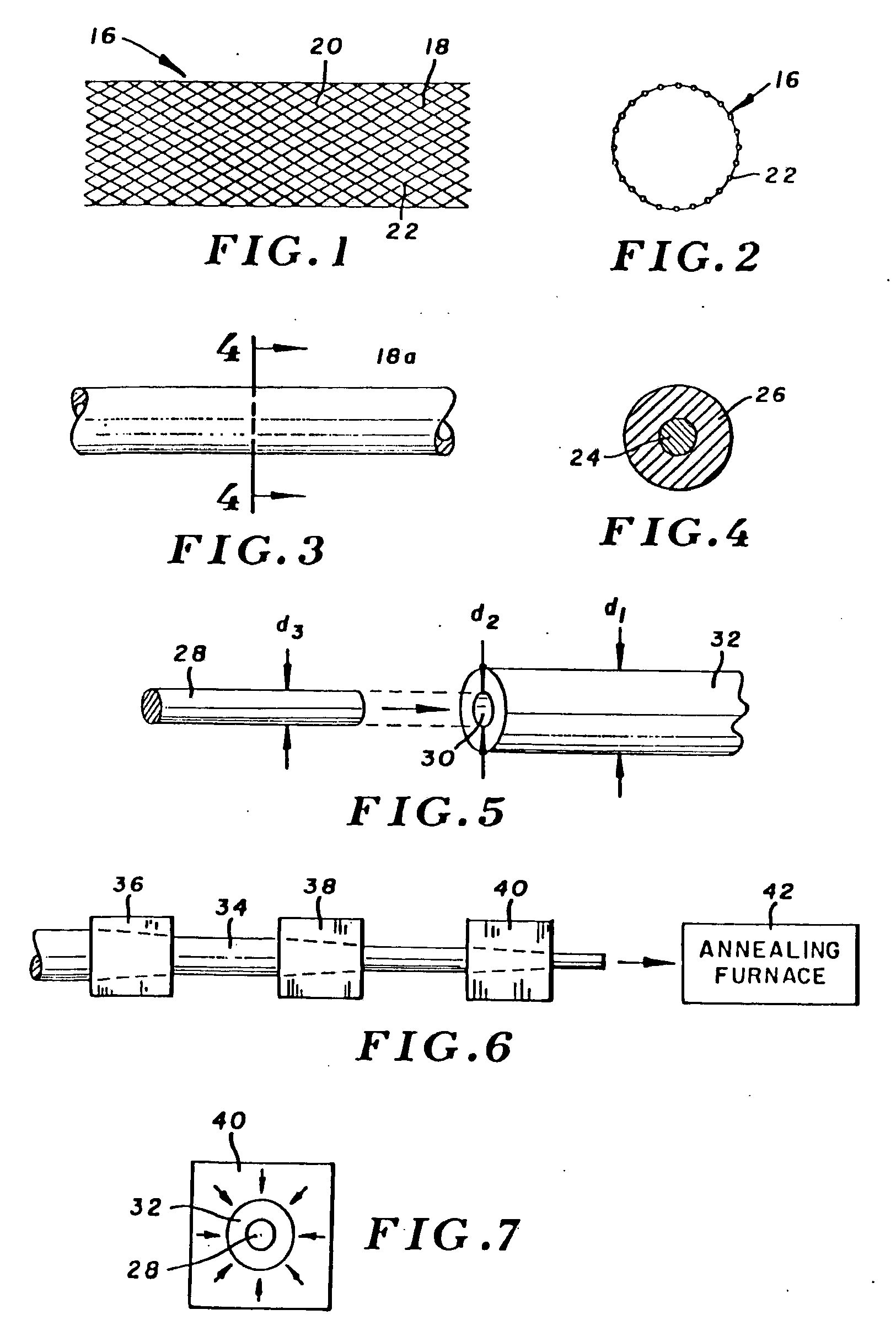
[0017]d. annealing the composite filament after cold-working, to substantially remove strain hardening and other stresses induced by the cold-working step;

Problems solved by technology

Consequently, prostheses constructed of these materials do not lend themselves well to fluoroscopic imaging.
Such stent, however, lacks the required elasticity, and would exhibit poor resistance to fatigue.
However, for many applications (e.g. in blood vessels), the stent is so small that such staples either would be too small to provide useful fluoroscopic imaging, or would adversely affect the efficiency and safety of deploying the stent or other prosthesis.
Further, given the small size of prostheses intended for blood vessel placement, this technique is unlikely to materially enhance radio-opacity, due to an insufficient amount and density of the gold or barium sulfate.

Method used


Image

  • Clad Composite Stent
  • Clad Composite Stent
  • Clad Composite Stent

Examples


example 1

[0087]An elongate tantalum core having a diameter of 0.46 inches (1.17 mm) was assembled into an Elgiloy alloy case having an outer diameter of 0.102 inches (2.6 mm) and an inner diameter of 0.056 inches (1.42 mm). Accordingly, the lateral cross-sectional area of the tantalum core was about 25% of the composite filament lateral cross-sectional area. Composite filaments so constructed were subjected to 5-6 alternating stages of cold-working and annealing, to reduce the outer diameters of the composite filaments to values within the range of 0.004-0.0067 inches. The tantalum core diameters were reduced to values in the range of 0.002-0.0034 inches. The composite filaments were formed into a stent suitable for biliary applications, and age hardened for up to five hours, at temperatures in the range of 900-1000° F.

example 2

[0088]Elongate cores of a platinum iridium alloy (20% by weight iridium), with initial core outer diameters of 0.088 inches, were inserted into annular Elgiloy cases with outer diameters of 0.144 inches and inside diameters of 0.098 inches. The resulting composite filaments were processed through about six cold-working and annealing cycles as in the first example, to reduce the outer filament diameter to values within the range of 0.00276 inches-0.0039 inches, and reducing the core outer diameter to values in the range of 0.0018-0.0026 inches. The core thus constituted 43% of the filament lateral cross-sectional area. The resulting filaments were formed into a small vascular stent, and age hardened for approximately three hours.

example 3

[0089]Composite filaments were constructed and processed substantially as in example 2, except that the core was formed of a platinum nickel alloy, with nickel 10% by weight.


PUM

PropertyMeasurementUnit
yield strengthaaaaaaaaaa
linear attenuation coefficientaaaaaaaaaa
weight percentaaaaaaaaaa

Abstract

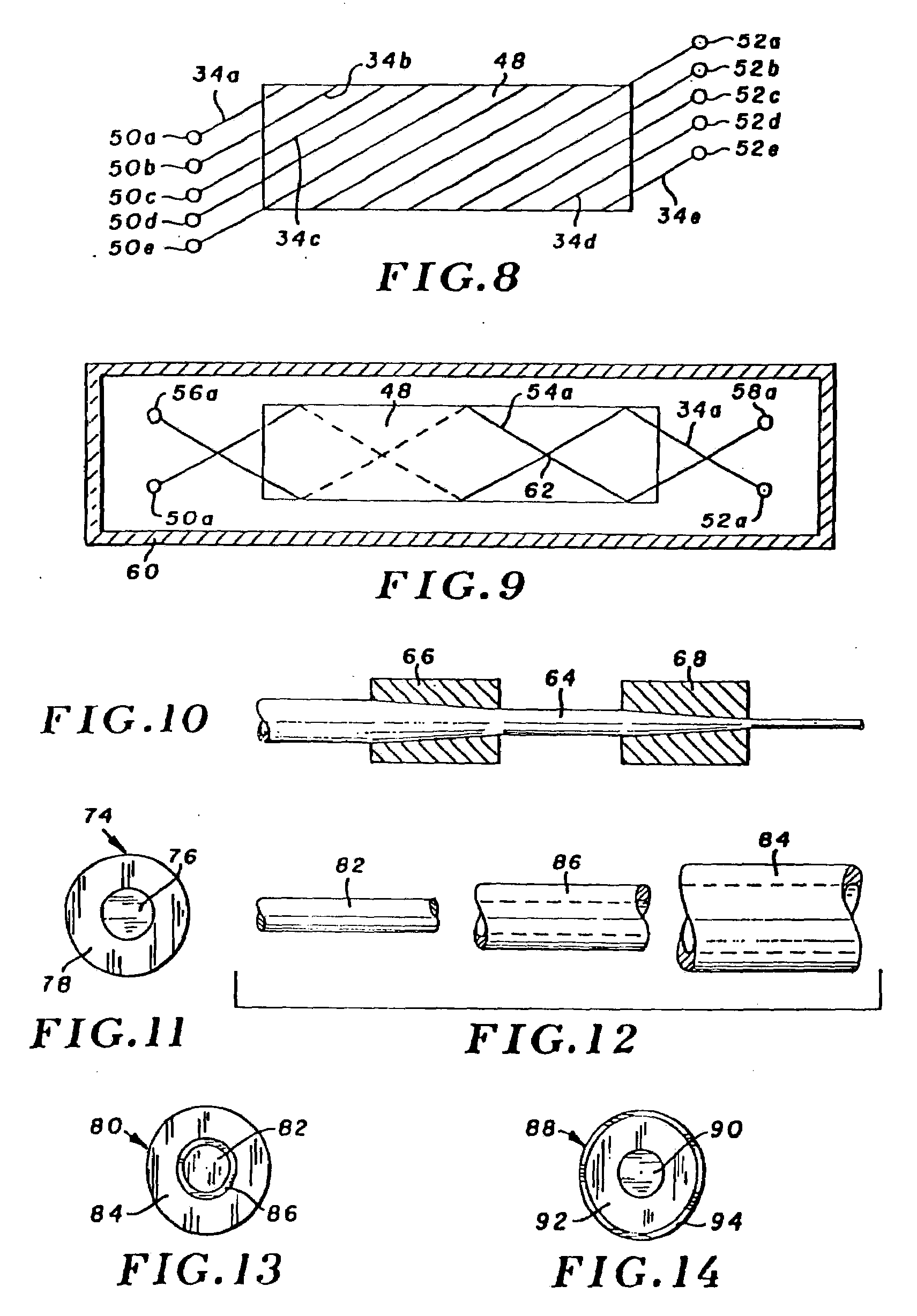
A body compatible stent is formed of multiple filaments arranged in at least two sets of oppositely directed helical windings interwoven with one another in a braided configuration. Each of the filaments is a composite including a central core and a case surrounding the core. In the more preferred version, the core is formed of a radiopaque and relatively ductile material, e.g. tantalum or platinum. The outer case is formed of a relatively resilient material, e.g. a cobalt / chromium based alloy. Favorable mechanical characteristics of the stent are determined by the case, while the core enables in vivo imaging of the stent. The composite filaments are formed by a drawn filled tubing process in which the core is inserted into a tubular case of a diameter substantially more than the intended final filament diameter. The composite filament is cold-worked in several steps to reduce its diameter, and annealed between successive cold working steps. After the final cold working step, the composite filament is formed into the desired shape and age hardened. Alternative composite filaments employ an intermediate barrier layer between the case and core, a biocompatible cover layer surrounding the case, and a radiopaque case surrounding a structural core.

Description

CROSS REFERENCE TO THE RELATED APPLICATION[0001]This patent application is a continuation-in-part of copending application Ser. No. 08 / 006,216, filed Jan. 19, 1993.BACKGROUND OF THE INVENTION[0002]The present invention relates to body implantable medical devices, and more particularly to stents and other prostheses configured for high radio-opacity as well as favorable mechanical characteristics.[0003]Recently several prostheses, typically of lattice work or open frame construction, have been developed for a variety of medical applications, e.g. intravascular stents for treating stenosis, prostheses for maintaining openings in the urinary tracts, biliary prostheses, esophageal stents, renal stents, and vena cava filters to counter thrombosis. One particularly well accepted device is a self-expanding mesh stent disclosed in U.S. Pat. No. 4,655,771 (Wallsten). The stent is a flexible tubular braided structure formed of helically wound thread elements. The thread elements can be constr...

Claims


Application Information

Patent Timeline
Patent Type & Authority Applications(United States)
IPC IPC(8): A61F2/06A61F2/90
CPCA61F2/90Y10T428/12333A61F2220/0016A61F2220/0008
Inventor MAYER, DAVID W.
Owner BOSTON SCI SCIMED INC
Learn More