

Film coating apparatus
a film coating and apparatus technology, applied in the field of film coating apparatus, can solve the problems of conventional apparatus not being able to cope with the increasing the rear surface of the substrate to be coated has to be rinsed, and the film thickness is uniform, so as to achieve uniform film thickness distribution, reduce the effect of high speed rotation and increase the diameter of the wafer
- Summary
- Abstract
- Description
- Claims
- Application Information
AI Technical Summary
Benefits of technology
Problems solved by technology
Method used
Image

Examples
second embodiment
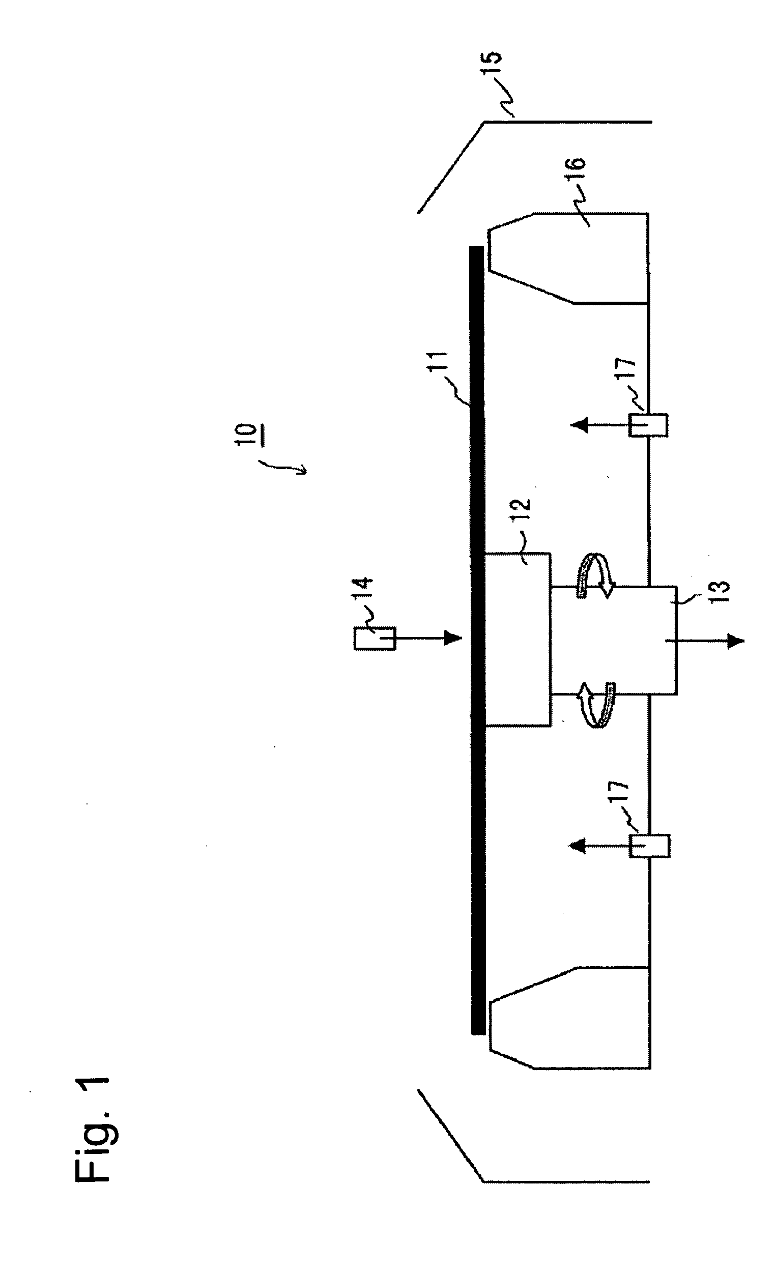
[0085]Next, the present invention will be explained with reference to FIG. 2.
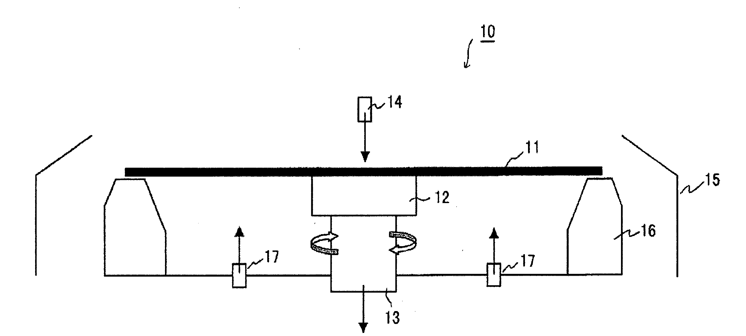
[0086]A film coating apparatus 20 illustrated in FIG. 2 includes a table 22 for retaining a substrate to be coated 21, a rotation mechanism 23 for rotationally driving the table 22, a resist nozzle 24 for supplying a resist liquid to a surface of the substrate to be coated 21, a cylindrical cup 25 configured to enclose the substrate to be coated 21 and a casing (not shown) for housing those.
[0087]The table 22 has a disk-shaped main table 221, a gas supplying nozzle positioned on the center of the table, for example, a sonic nozzle 222, a ring-shaped projection 223 positioned on the upper periphery of the main table 221 and a plurality of clamp pins 224 positioned on the outer circumference side of the ring-shaped projection 223. The table 22, as describe below, retains the substrate to be coated 21 without contacting with the rear surface of the substrate to be coated 21. The gas is supplied to the sonic no...
first embodiment
[0094]In a state illustrated in FIG. 3B, the gas ejected from the sonic nozzle 222 flows toward the outer circumference of the substrate to be coated 21, as shown by the right-pointing arrow in the enlarged illustration, in the space between the substrate to be coated 21 and the main table 221. The gas passage formed by the substrate to be coated 21 and the main table 221 is narrowed by the ring-shaped projection 223 formed on the upper surface of the main table 221, and the gas flow speed at the point is increased (for example, the flow speed is 7 m / sec). As a result, the gas is exhausted from the outer circumference of the substrate to be coated 21 at a higher speed of flow than the speeds of flow at other portions. Then, the substrate to be coated 21 can be fixed securely in an absolute location (vacuum holding and retain) against the main table 221 by Bernoulli effects without making at least the rear surface of the substrate to be coated 21 contact with the table. Namely, the o...
third embodiment
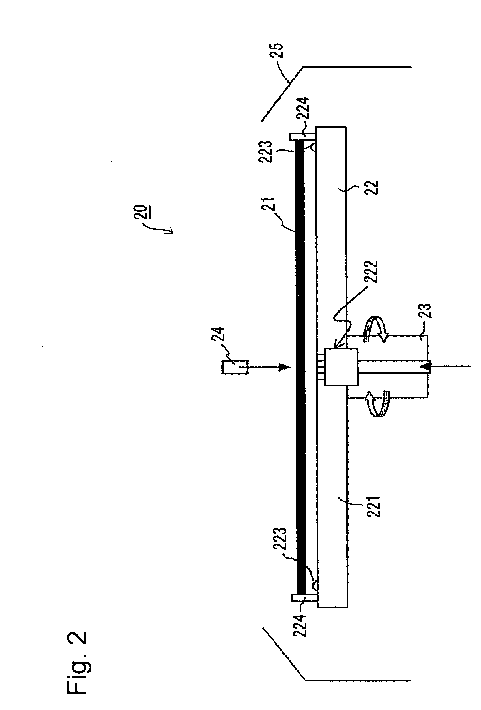
[0097]Next, a film coating apparatus according to the present invention will be explained with reference to FIG. 4.
[0098]A film coating apparatus 40 illustrated in FIG. 4 includes a table (not shown) for retaining a substrate to be coated 41, a casing 42 for housing a resist nozzle for supplying a resist liquid and the like, a pump 43 for supplying the resist liquid to the resist nozzle, a deaerating film 44 for removing oxygen and the like included in the resist liquid, a resist supply piping 45 for connecting those, a gas supply section 46 for introducing a gas into the casing 42 and a gas exhaust section 47 for exhausting the gas in the casing 42.
[0099]In the present embodiment, a material having a low gas permeability coefficient is used for the resist supply piping 45, and the deaerating film 44 is placed at the upper position of the pump 43 to remove oxygen and moisture contained in the resist liquid.
[0100]In addition, in the present embodiment, the exhaust is conducted while ...
PUM
| Property | Measurement | Unit |
|---|---|---|
| Diameter | aaaaa | aaaaa |
| Speed | aaaaa | aaaaa |
| Height | aaaaa | aaaaa |
Abstract
Description
Claims
Application Information