Imaging optical unit, inspection method for the same, and image reading apparatus

a technology of optical units and inspection methods, applied in the direction of optical elements, applications, instruments, etc., can solve the problems of difficult to specify which optical elements, difficult to measure the change of shape of optical elements, and difficult to measure the optical performance of off-axial optical systems including optical elements having reflection surfaces. to achieve the effect of facilitating the measurement of a change in shap

Inactive Publication Date: 2009-11-12
CANON KK
View PDF0 Cites 4 Cited by
  • Summary
  • Abstract
  • Description
  • Claims
  • Application Information

AI Technical Summary

Benefits of technology

[0025]It is an object of the present invention to provide an inspection method for an imaging optical unit that facilitates measuring a change in shape of each optical el

Problems solved by technology

However, the off-axial optical system including the optical element having the reflection surface has a tendency to decrease its optical performance largely if a shape of the optical element changes or an off-center error occurs in the manufacturing process of the optical element.
When the optical elements are housed and held in the case, it is very difficult to measure changes of shapes of the optical elements and an assembly error in the state where the optical elements are held, because the optical path is bent by the reflection and the reflection surfaces face eac

Method used


Image

  • Imaging optical unit, inspection method for the same, and image reading apparatus
  • Imaging optical unit, inspection method for the same, and image reading apparatus
  • Imaging optical unit, inspection method for the same, and image reading apparatus

Examples


embodiment 1

[0042]Hereinafter, the embodiments of the present invention are described. First, a manner of attaching an off-axial optical element having an off-axial reflection surface to the imaging optical system (off-axial optical system) is illustrated.

[0043]Note that the same members or members having the same function are denoted by the same reference numeral so as to avoid confusion.

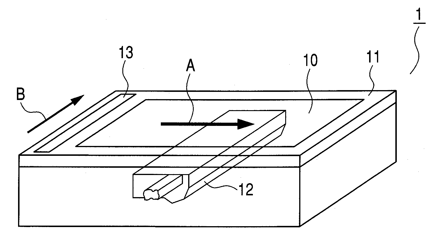
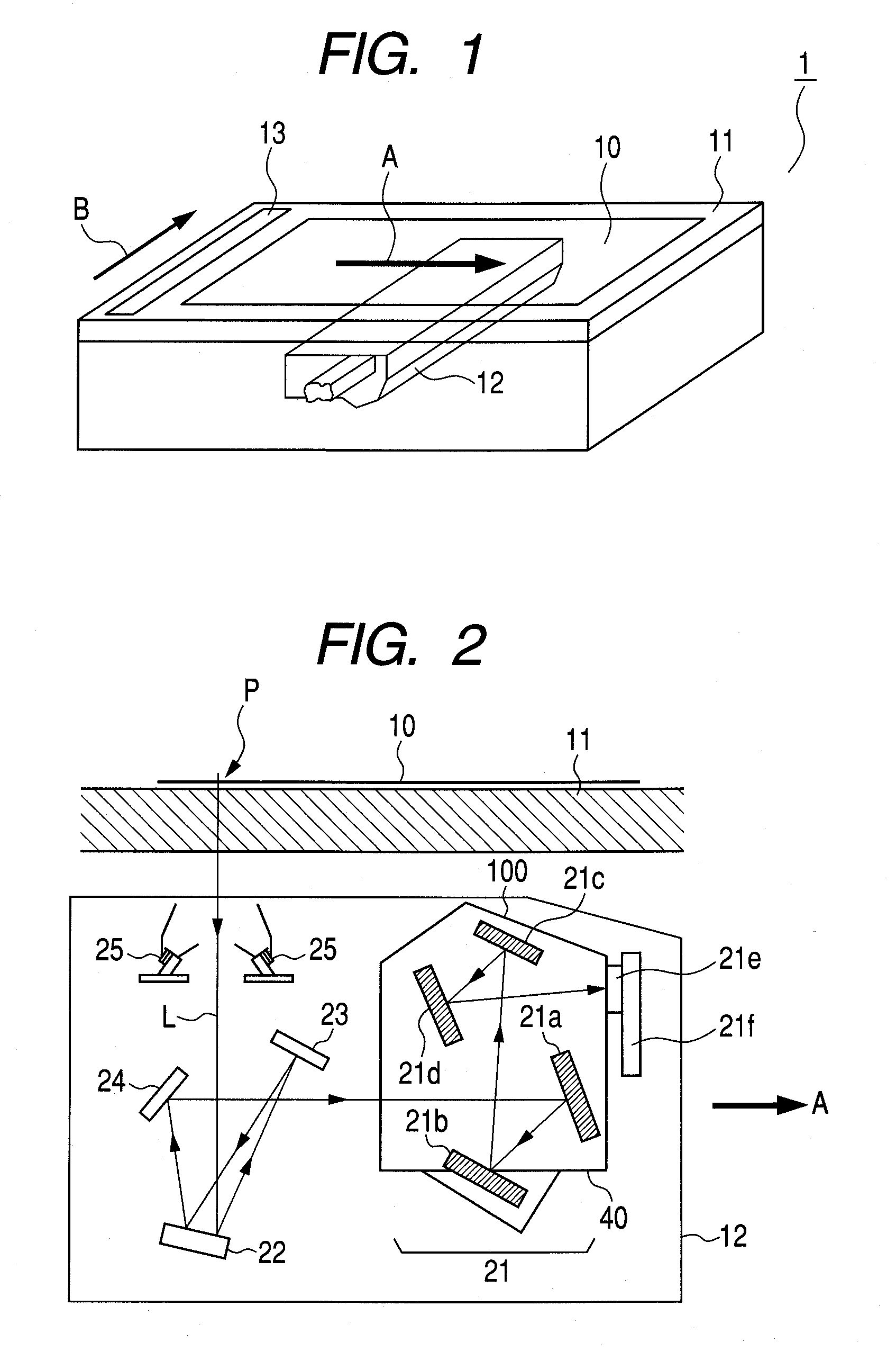
[0044]FIG. 1 is an outline view of an image reading apparatus according to Embodiment 1 of the present invention.

[0045]In FIG. 1, numeral 1 denotes the image reading apparatus. An original 10 has an image formed thereon and is placed on a glass original table 11. In a carriage (unit) 12, an imaging optical system (not shown) for reading the original 10, multiple reflection mirrors (not shown), an illumination system (not shown) for illuminating the original 10, and the like are housed. Numeral 13 is a white plate.

[0046]In the image reading apparatus 1 illustrated in FIG. 1, the carriage 12 is first positioned ...

embodiment 2

[0105]FIG. 6 is an explanatory diagram illustrating a manner (inspection method) of measuring a reflection type off-axial optical element according to Embodiment 2 of the present invention.

[0106]This embodiment is different from Embodiment 1 described above in that the mirror surface 30b on the back side of the reflection type off-axial optical element 21a is formed to have a spherical surface shape performing a condensing action or a diverging action. Other structure and optical action are the same as those of Embodiment 1 so that the same effect can be obtained.

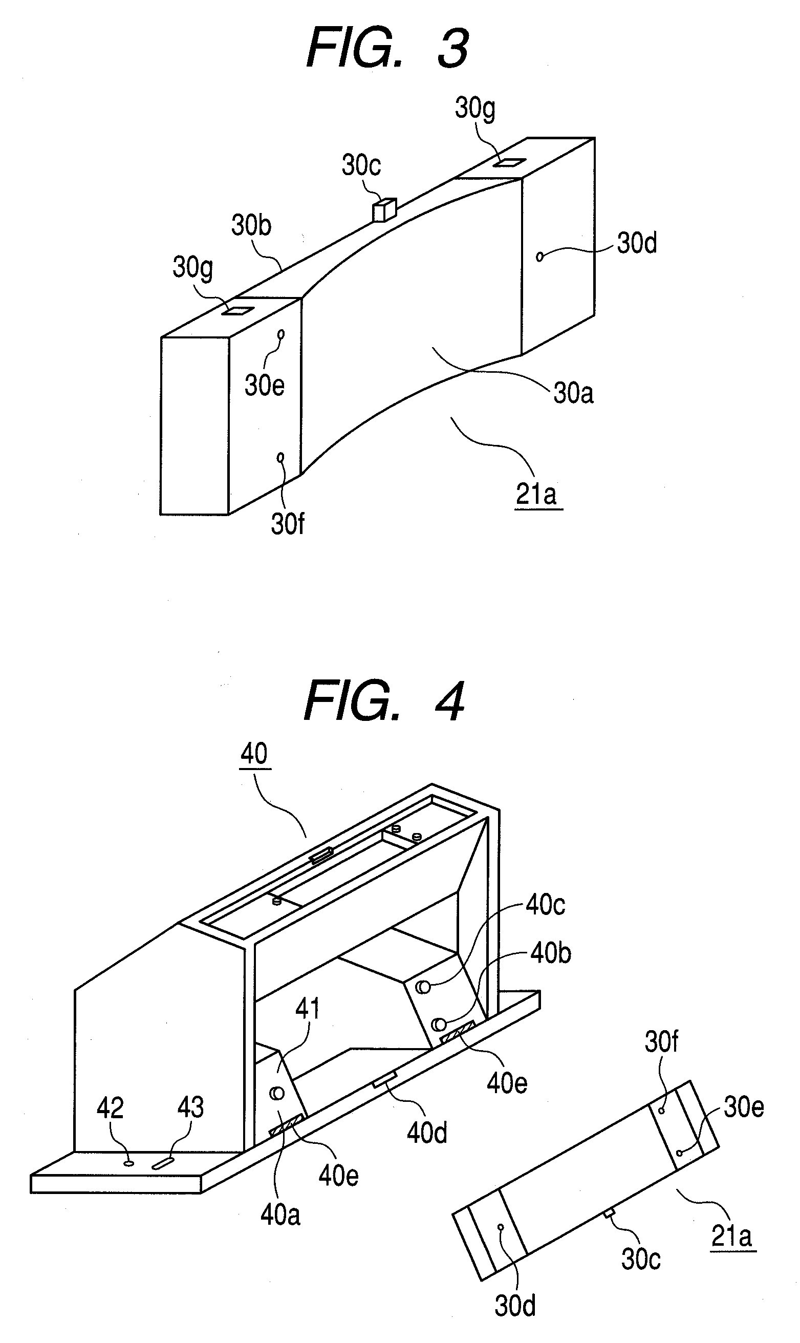
[0107]More specifically, in FIG. 6, the reflection type off-axial optical element 21a has the mirror surface (mirror surface part) 30b on the back side made of the spherical surface shape performing the condensing action or the diverging action.

[0108]Further, the mirror surface 30b having the curved surface shape is formed to have the same shape as an absolute value of an on-axis power of the optical surface 30a.

[0109]In t...

embodiment 3

[0119]FIG. 8 is a schematic diagram of a main part of an image reading apparatus of Embodiment 3 of the present invention.

[0120]The image reading apparatus according to this embodiment has a structure in which the imaging optical device 100 and the inspection method described above are incorporated, and a distortion of the off-axial optical element 21a during continuous operation can be monitored by a distortion monitoring portion 120.

[0121]More specifically, in FIG. 8, the carriage 12 has the case 40 in which the imaging optical system 21 made up of the four reflection type off-axial optical elements 21a to 21d, the line sensor 21e, the substrate 21f and the like are housed.

[0122]The back side of the reflection type off-axial optical element 21a constituting an element of the imaging optical system 21 is finished to have the mirror surface of the spherical surface shape (mirror surface state) 30b. In addition, the distortion monitoring portion 120 for monitoring the distortion of t...


PUM


Abstract

Provided is an imaging optical unit used in an image reading apparatus for imaging image information on a photoelectric conversion element. The imaging optical unit includes a case and an imaging optical system having multiple reflecting members housed and disposed in the case. The reflecting member has a mirror surface for detecting assembly performance in the case on a side opposite to an optical surface for performing an imaging action. A light beam from a light source unit is projected to the mirror surface of the reflecting member and reflection light from the mirror surface is used for detecting one of a shift of posture and a distortion of the reflecting member.

Description

BACKGROUND OF THE INVENTION[0001]1. Field of the Invention[0002]The present invention relates to an imaging optical unit and an inspection method for the same. Particularly in an image scanner, a digital copying machine, a facsimile, or the like, the present invention can be used suitably for reading image information of a monochrome image or a color image using a signal from a line sensor (image pickup element or photoelectric conversion element).[0003]2. Description of the Related Art[0004]Conventionally, various flat bed type image scanners have been proposed as an image reading apparatus (image scanner) for reading image information on a surface of an original (see Japanese Patent Application Laid-Open No. H03-113961).[0005]In the flat bed type image scanner, an imaging lens (imaging optical system) and a line sensor (CCD) are fixed while only a reflection mirror disposed in an optical path is moved so that the surface of the original is scanned by slit exposure for reading imag...

Claims


Application Information

Patent Timeline
IPC IPC(8): G01N21/55G01N21/86G02B17/06H04N1/028
CPCG01N21/45G01N2021/8427H04N1/00002H04N1/00013H04N1/00018H04N1/193H04N1/00037H04N1/00053H04N1/00058H04N1/1017H04N1/00029
Inventor MORI, SEIICHIRO
Owner CANON KK
Why Eureka
Try Eureka