
Temperature sensing circuit for low voltage operation

a temperature sensing circuit and low-voltage technology, applied in the field of semiconductor ic, can solve problems such as data loss, system instability, or even chip burnout, and increase the manufacture cos

Inactive Publication Date: 2009-11-12
TAI JY DER DAVID
View PDF7 Cites 14 Cited by
  • Summary
  • Abstract
  • Description
  • Claims
  • Application Information

AI Technical Summary

Benefits of technology

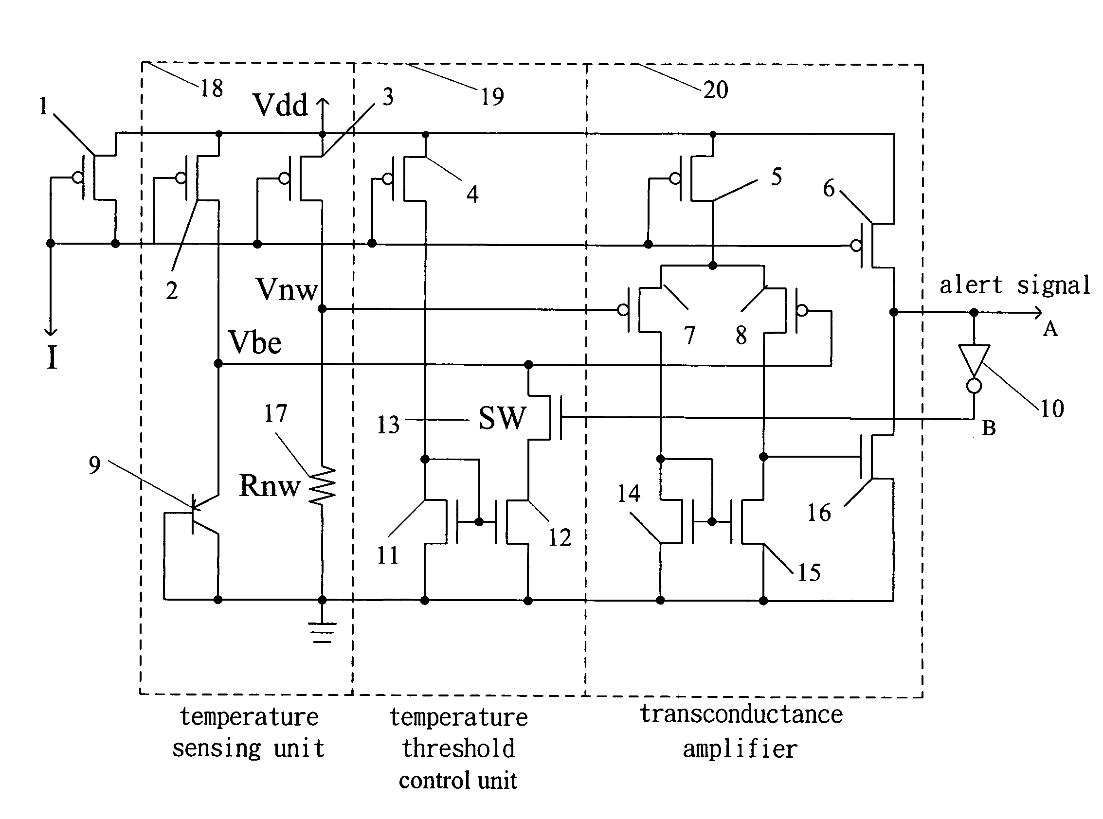
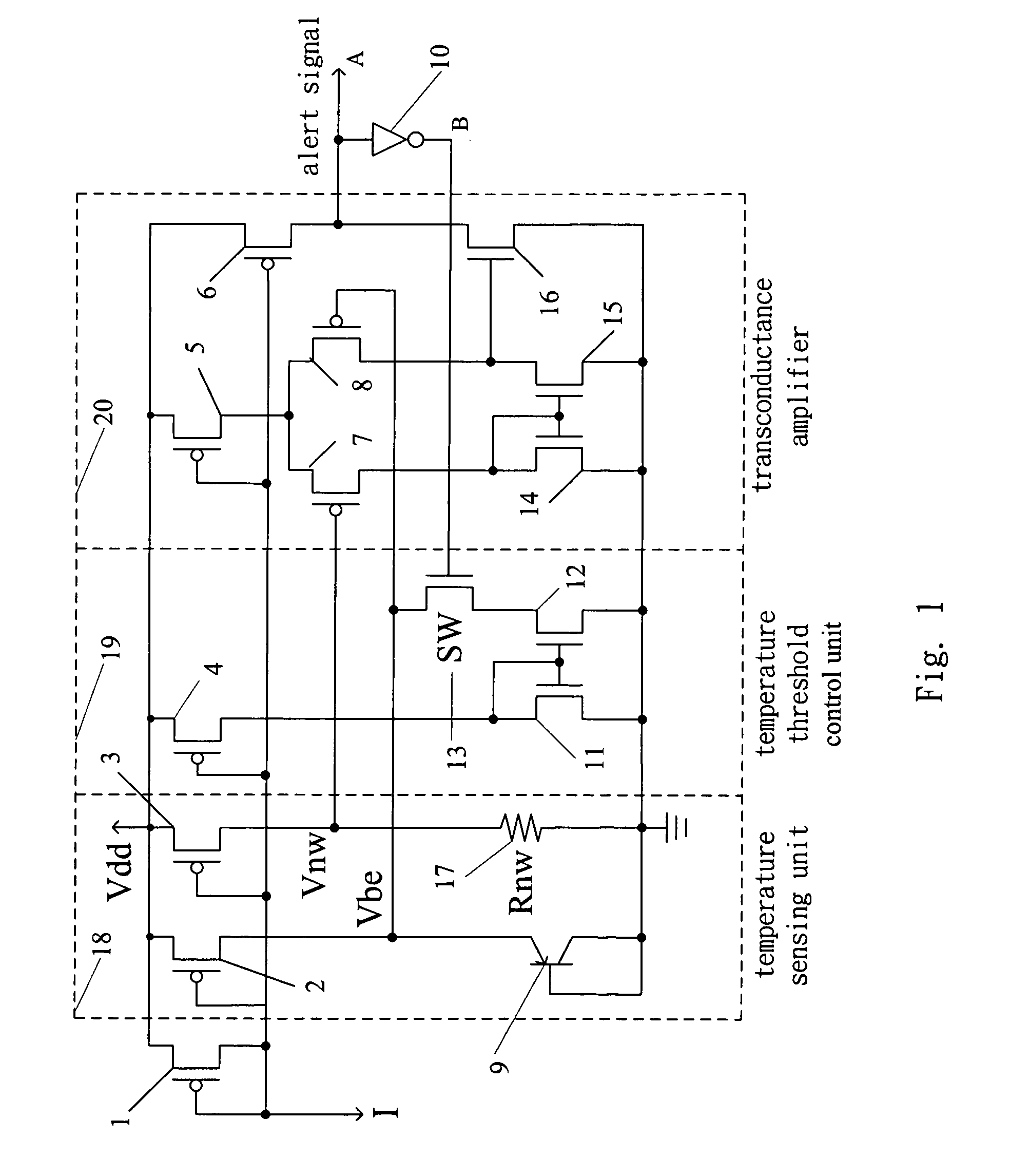
[0007]The primary objective of the present invention is to provide a temperature sensing circuit which is mainly comprised by a temperature sensing unit, a temperature threshold control unit and a transconductance amplifier, wherein the temperature threshold control unit directly controls the state of the temperature sensing unit. The present invention not only can precisely detect temperature of the IC but also can persistently send out an over-temperature alert until the temperature is lowered to a specified value. Further, the transconductance amplifier makes the present invention able to operate under low supply voltage.

Problems solved by technology

However, overheating of any electronic product may result in data loss, system instability, or even chip burnout.
An external temperature sensing element not only increases the manufacture cost, it also can not measure the temperature of the chip precisely.
Thus, the current temperature sensing circuit cannot apply to a low-voltage IC environment.
Further, the current temperature sensing circuit itself lacks an intrinsic temperature threshold control function.
Therefore, the conventional technology not only inconveniences designers, but also increases the cost of manufacturing.

Method used


Image

  • Temperature sensing circuit for low voltage operation
  • Temperature sensing circuit for low voltage operation
  • Temperature sensing circuit for low voltage operation

Examples


Embodiment Construction

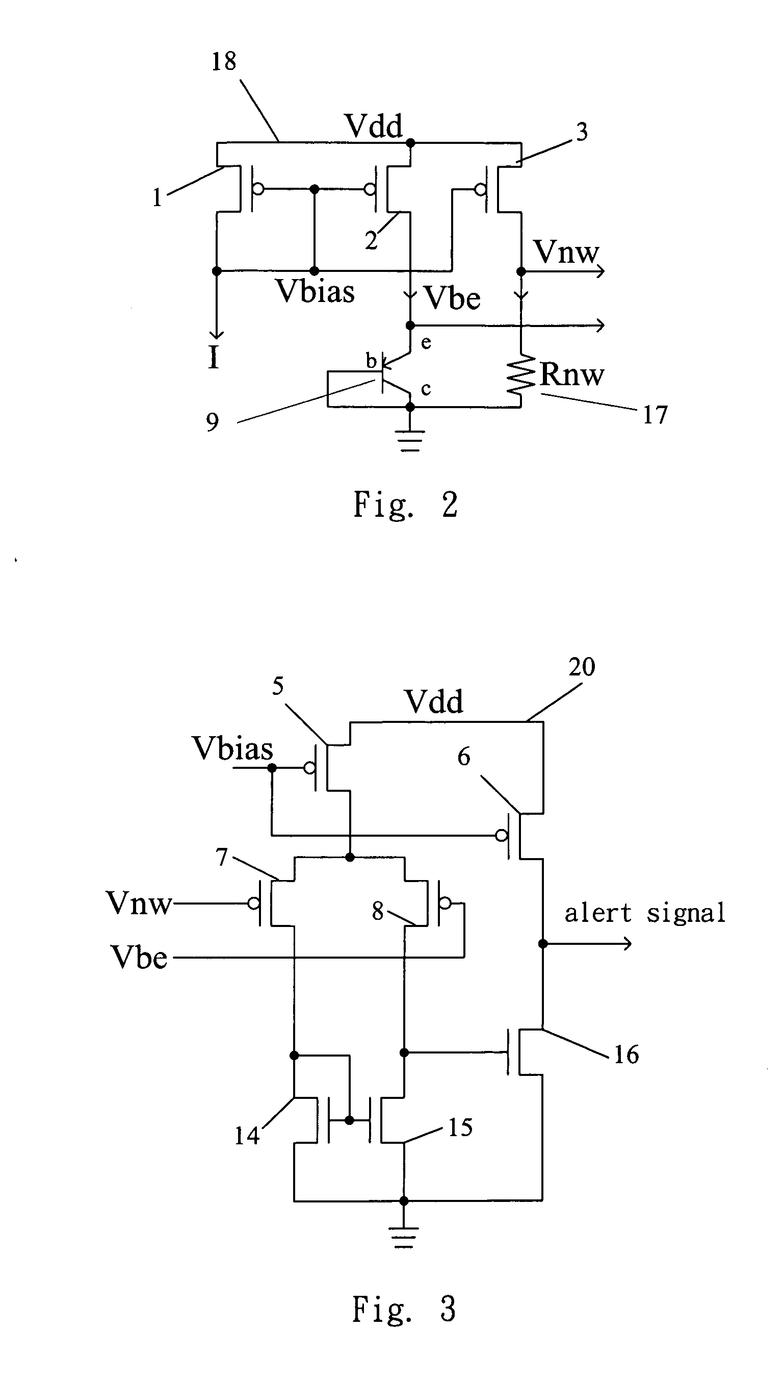
[0014]The present invention discloses a temperature sensing circuit which is able to operate under a low voltage IC environment. Not only can the present invention detect the temperature of circuits, but it can also send out an over-temperature alert persistently until the temperature is lowered to a specified value. Refer to FIG. 1 a diagram schematically showing the circuit of a preferred embodiment of the present invention. The circuit of the present invention comprises: a temperature sensing unit 18, a temperature threshold control unit 19 and a transconductance amplifier 20. Refer to FIG. 2. The temperature sensing unit 18 senses temperature via detecting voltage. The temperature sensing unit further comprises the following elements: a PMOS transistor 1 with the gate and drain thereof coupled to a current output terminal and the source thereof coupled to a Vdd voltage; a PMOS transistor 2 with the gate thereof also coupled to the current output terminal and the source thereof a...


PUM


Abstract

The present invention discloses a temperature sensing circuit which is adaptive toward low voltage IC environment, it mainly comprises: a temperature sensing unit, a temperature threshold control unit and a transconductance amplifier. The temperature sensing unit includes a bipolar transistor and PMOS transistors, and senses temperature via detecting voltage. The temperature threshold control unit includes PMOS transistors and NMOS transistors, and makes an over-temperature alert signal persistently sent out until temperature is lowered to a specified value when the temperature sensing unit detects an over-temperature state. The transconductance amplifier includes PMOS transistors and NMOS transistors, and makes the temperature sensing circuit of the present invention adapt to a low voltage IC environment. Further, the circuit architecture of the present invention does not require any use of operational amplifier or band-gap voltage reference source. Therefore, the present invention can reduce the production and design cost.

Description

BACKGROUND OF THE INVENTION[0001]1. Field of the Invention[0002]The present invention relates to a semiconductor IC, particularly to a temperature sensing circuit having a temperature range control unit.[0003]2. Description of the Related Art[0004]With new electronic products persistently emerging, more and more functions are integrated into a single product. For example, the digital camera and MP3 player are being integrated into a mobile phone or many multimedia devices are being integrated into a notebook computer. As a result, manufacturers need to incorporate more chips into a single electronic product to satisfy such functional integration. In addition, with the increasing of CPU clock frequency at the same time, more heat is generated within the electronic product. However, overheating of any electronic product may result in data loss, system instability, or even chip burnout. An external temperature sensing element not only increases the manufacture cost, it also can not mea...

Claims


Application Information

Patent Timeline
IPC IPC(8): G01K7/00
CPCG01K7/015G01K3/005
Inventor TAI, JY-DER DAVID
Owner TAI JY DER DAVID
Learn More