Energy storage and generation

a technology for energy storage and generation, applied in the direction of greenhouse gas reduction, container discharge methods, lighting and heating apparatus, etc., can solve the problems of pumped hydro, inability to meet the needs of customers, and disadvantages, so as to minimise the effect of environmental impa

Inactive Publication Date: 2009-11-19
HIGHVIEW ENTERPRISES LTD
View PDF28 Cites 141 Cited by
  • Summary
  • Abstract
  • Description
  • Claims
  • Application Information

AI Technical Summary

Benefits of technology

[0036]The energy storage system may maximise the use of, and minimise the modification of, current available and mature technologies for cryogen formation, such as air liquefaction plants.
[0037]If the cryogen comprises liquid air, the liquid air may be produced by an air liquefaction plant and supplied to the CES at off-peak hours. In the meantime, other products such as O2, N2, Ar and CO2 in both gas and liquid states could be produced as commercial products if needed. The efficiency of the production of the cryogen may be improved by using waste cold from other sources such as from the regasification of LNG (liquid natural gas).
[0039]The cryogen may be expanded by heating. For example, the cryogen may be heated by thermal sources including ambient, geothermal, waste heat from power plants and / or other waste heat resources to heat the cryogenic working fluid and generate electricity during peak hours. The thermal sources may not previously have been utilised for electricity generation because the temperature difference between the working fluid and heat source would have been considered insufficient. The working fluid may be superheated by the waste heat. The waste heat may have originated from power plants or from the compression process of the input gas or even from the waste gas stream after being heated to ambient temperature by ambient air. To increase the energy density of the working fluid, the gaseous input may be at a high pressure before expansion because the ideal work per unit mass of gaseous input for an isothermal expansion for an ideal gas, WT, is given byWT=RTln(PinPout)where R, T, Pin, and Pout are the universal constant, gas temperature, and injection and exhaust pressures, respectively. Moreover, the cryogen may be pumped as a liquid to a high working pressure because little work is consumed in the pressurization of liquid. On the other hand, the gas temperature may be as high as possible before expansion. Use could be made of the waste heat contained in the flue gas from power plants for heating the cryogen. Most effectively, the ambient air could be used to heat the cryogen to approximately the environmental temperature and the waste heat could then be used to heat the working fluid further to improve the energy efficiency of the entire system. Because the temperature difference between the cryogen and ambient temperature is high, waste heat which previously would have been considered a poor source of energy can be used as a source of energy to heat the cryogen.
[0046]The present invention may make simultaneous use of ‘cold’ energy and ‘waste’ heat. By recovering the ‘cold’ energy from the expansion of the stored cryogen and using it to enhance the production of more cryogen whilst the system is operating in electricity generation mode, the efficiency of the system as a whole is increased. Cold energy is as useful in this system as hot energy. In addition the CES uses energy in the ambient air (heat) or water to heat the cryogen to close to the ambient temperature, followed by further heating with waste heat from, for example, flue gas and steam venting to the environment from a power generation plant. Also, heat released from the compression of gaseous input can also be recovered and used to heat the cryogen. The heat applied to the cryogen causes it to expand and this drives the cryogen.
[0051]When a non-polluting source of energy is used to power the system, the system is environmentally benign with a potential to reverse environmental contamination by separating environmentally detrimental gases, such as CO2 and other contaminants, associated with the burning of fossil fuels from the gaseous input.
[0052]The system of the present invention does not involve any combustion process so it will not cause any emissions. The only working fluid is the cryogen. The effect on the environment is also minimised because less CO2 and other environmentally detrimental gas components such as NOX are produced or used.

Problems solved by technology

This is due to the intermittent nature of the sources of renewable energy; the source is not always available over an extended period of time.
Such a disadvantage has become an obstacle to the green electricity industry.
However, a scarcity of available sites for two large reservoirs and one or more dams is the major drawback of pumped hydro.
A long lead time for construction (typically ˜10 years) and environmental issues (e.g. removing trees and vegetation from the land prior to the reservoir being flooded) are two other major drawbacks of the pumped hydro system.
It cannot be used in other types of power plants such as coal-fired, nuclear, wind turbine or solar photovoltaic plants.
In addition, the combustion of fossil fuels leads to emission of contaminates such as nitrogen oxides and carbon oxides which render the CAES less attractive.
Also, similar to pumped hydro systems, CAES suffers from a reliance on favourable geography such as caverns.
CAES can only be economically feasible for power plants that have nearby rock mines, salt caverns, aquifers or depleted gas fields.
In addition, a major barrier for the CAES is the relatively low pressures that can be achieved, typically 40-60 bar.
However, until recently, utility battery storage has been rare because of the low energy densities, high maintenance costs, short lifetimes, limited discharge capabilities and toxic remains associated with such systems.
The major problems confronting the implementation of SMES units are the high cost and environmental issues associated with the strong magnetic fields employed.
The disadvantages of these systems are their short duration, relatively high frictional losses (windage) and low energy densities.
Traditional flywheel systems with conventional metal rotors lack the necessary energy density to be considered seriously for large-scale energy storage applications.
The major disadvantages of capacitors as energy storage systems are, similar to flywheels, their short duration and high energy dissipation due to self-discharge loss.
However, all these engines have environmental problems.
Contaminates (e.g. CO2, NOx and particulates) are inevitably produced in combustion processes.
Nuclear power systems not only produce nuclear waste pollution and provide a radiation risk but also are at least an order of magnitude more expensive than other power systems.

Method used


Image

  • Energy storage and generation
  • Energy storage and generation
  • Energy storage and generation

Examples


Embodiment Construction

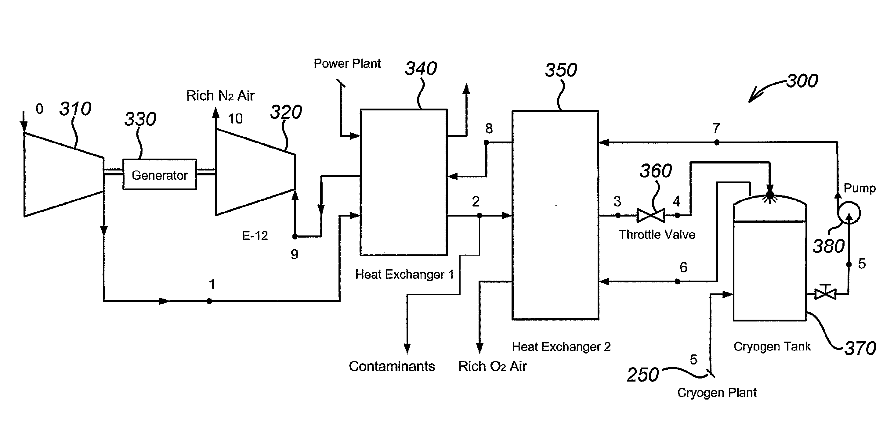
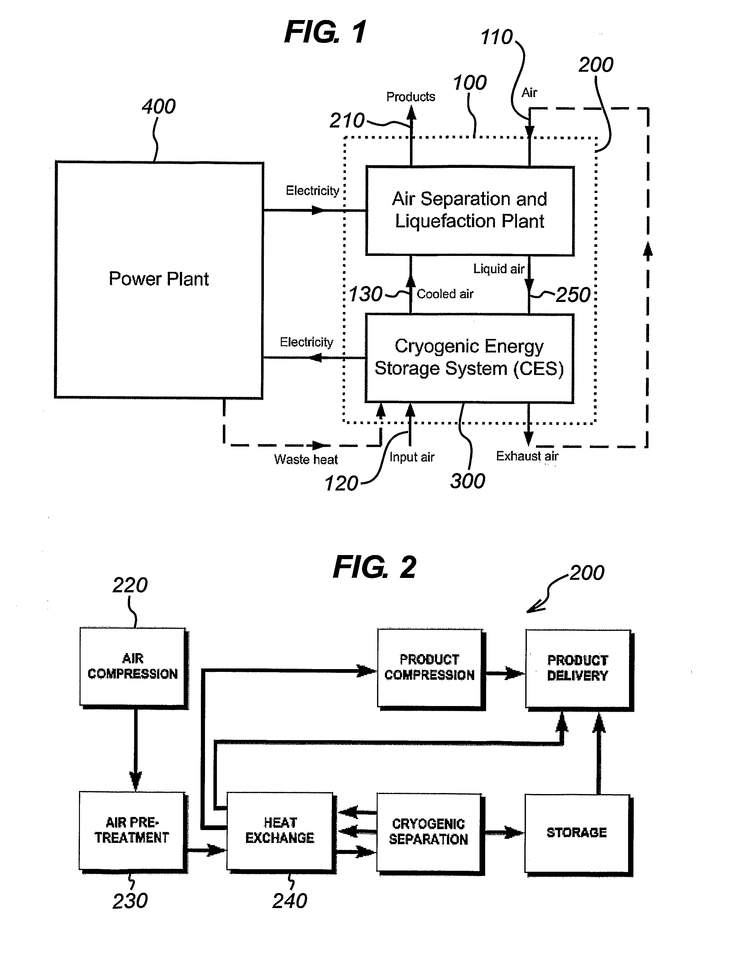
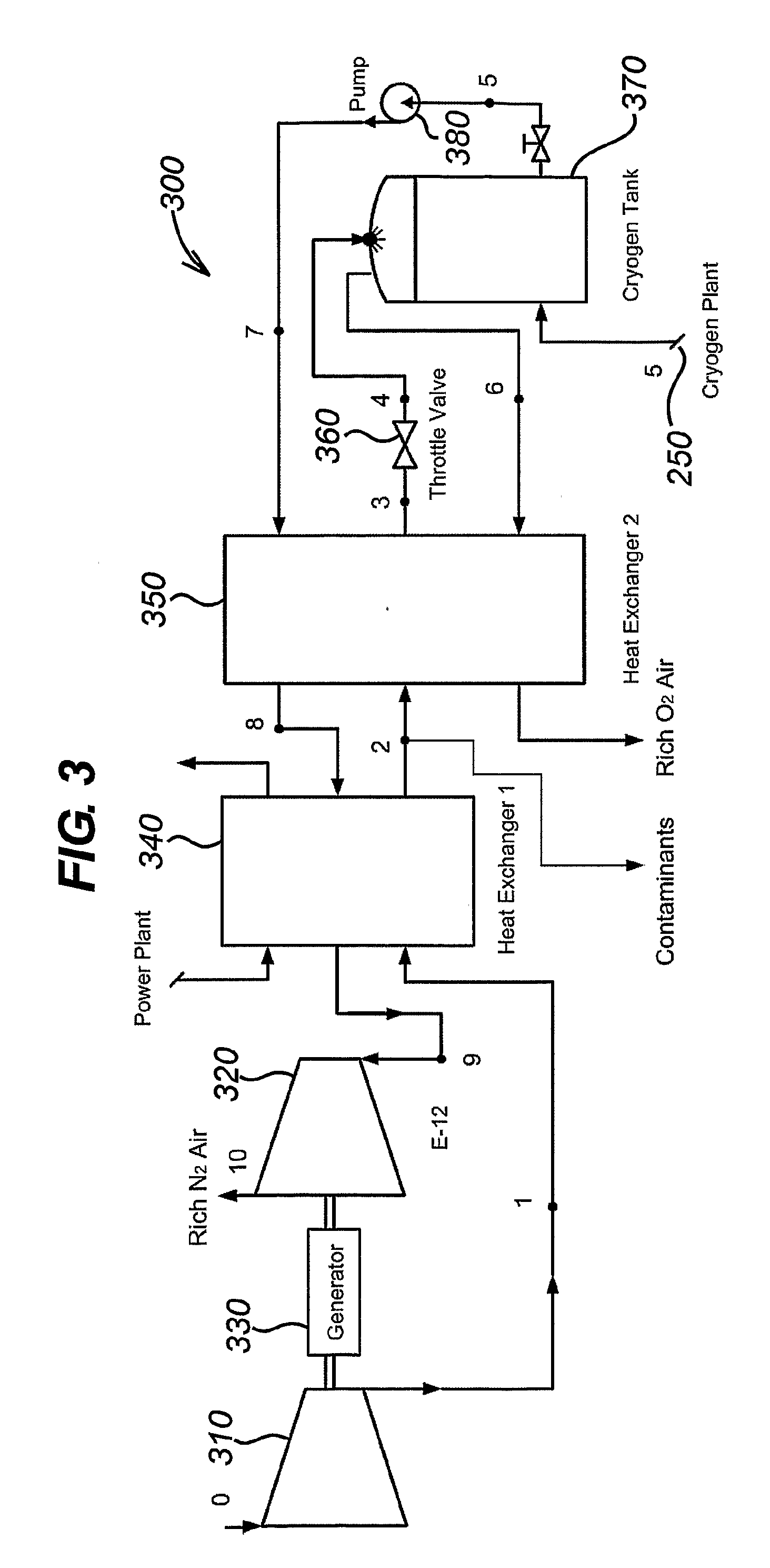
[0110]A conceptual design of the energy storage system of the present invention is shown in FIG. 1. The whole system is shown within dotted box 100. System 100 consists of two major parts: an air liquefaction part 200, and a Cryogenic Energy Storage unit (CES) 300. In off-peak hours, surplus electricity is fed to the air liquefaction plant 200 to produce liquid air, which is then used in peak hours by the CES 300 to generate electricity. The power plant 400 and the whole energy storage system 100 only have to exchange electricity, so no modification of the power plant 400 is needed thus ensuring maximum flexibility. At the same time, any available waste heat 410 from the flue gas of the power plant 400 can be used by the CES 300 to heat the working fluid.

[0111]Within the energy storage system 100, there are two major air streams. One stream 110 feeds air to the air liquefaction plant 200 to be liquefied and stored as liquid air in a cryogen tank. During peak time the liquid air is p...


PUM


Abstract

The present invention concerns systems for storing energy and using the stored energy to generate electrical energy or drive a propeller (505). In particular, the present invention provides a method of storing energy comprising: providing a gaseous input, producing a cryogen from the gaseous input; storing the cryogen; expanding the cryogen; using the expanded cryogen to drive a turbine (320) and recovering cold energy from the expansion of the cryogen. The present invention also provides a cryogenic energy storage system comprising: a source of cryogen; a cryogen storage facility (370); means for expanding the cryogen; a turbine (320) capable of being driven by the expanding cryogen; and means (340, 350) for recovering cold energy released during expansion of the cryogen.

Description

FIELD OF THE INVENTION[0001]The present invention concerns systems for storing energy and using the stored energy to generate electrical energy or drive a propeller.BACKGROUND TO THE INVENTION[0002]Electrical energy storage systems store base-load energy during off-peak periods and use the stored energy to provide electrical power during peak periods. Such systems are essential to the power generation industries. In conventional power generation systems, an energy storage system can provide substantial benefits including load following, peaking power and standby reserve. By providing spinning reserve and a dispatched load, electrical energy storage systems can increase the net efficiency of thermal power sources while reducing harmful emissions.[0003]Electrical energy storage systems are critically important to intermittent renewable energy supply systems such as solar photovoltaic and wind turbine supply systems. This is due to the intermittent nature of the sources of renewable en...

Claims


Application Information

Patent Timeline
Patent Type & Authority Applications(United States)
IPC IPC(8): F17C9/04F02C1/02F02C6/14
CPCF01D15/005F25J1/0045F01K3/00F01K13/00F01K15/04F02C1/05F02C6/14F03D9/028F05B2210/12F25J1/0012F25J1/004F25J1/0221F25J1/0234F25J1/0242F25J1/0251F25J1/0281F25J3/04018F25J3/04078F25J3/04115F25J3/04169F25J3/04224F25J3/04496F25J3/04533F25J3/04593F25J3/04612F25J3/04618F25J3/04836F25J2205/62F25J2210/40F25J2215/40F25J2230/06F25J2230/20F25J2230/30F25J2235/02F25J2240/10F25J2240/90F25J2245/40F25J2260/20Y02E60/15Y02T50/672F05D2210/12Y02E10/72F01D15/04F25J1/0228F03D9/17Y02E60/16Y02T50/60Y02E70/30F25J2210/42F25J2210/62F03D9/25F02C1/002F17C9/04
Inventor CHEN, HAISHENGDING, YULONGPETERS, TOBYBERGER, FERDINAND
Owner HIGHVIEW ENTERPRISES LTD
Why Eureka
Try Eureka