Fluid control system
a control system and flue gas technology, applied in the direction of flue gas control, process and machine control, instruments, etc., can solve the problems of difficult use for applications controlling the flow rate over a broad flow rate range, complicated work, and time-consuming, etc., to achieve easy installation work, shorten work time, and reduce the space of the installation location
- Summary
- Abstract
- Description
- Claims
- Application Information
AI Technical Summary
Benefits of technology
Problems solved by technology
Method used
Image
Examples
first embodiment
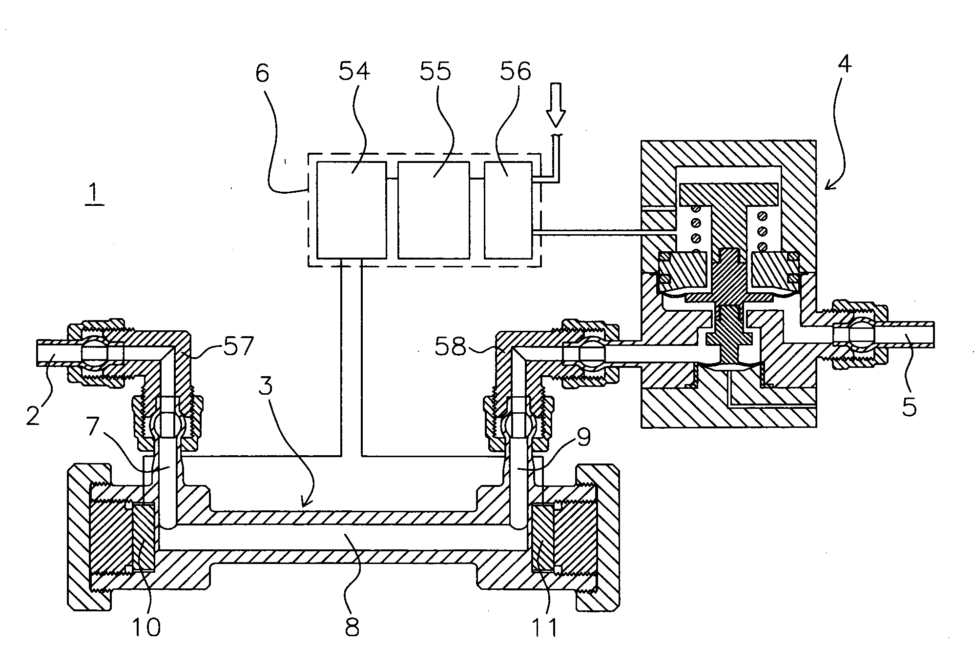
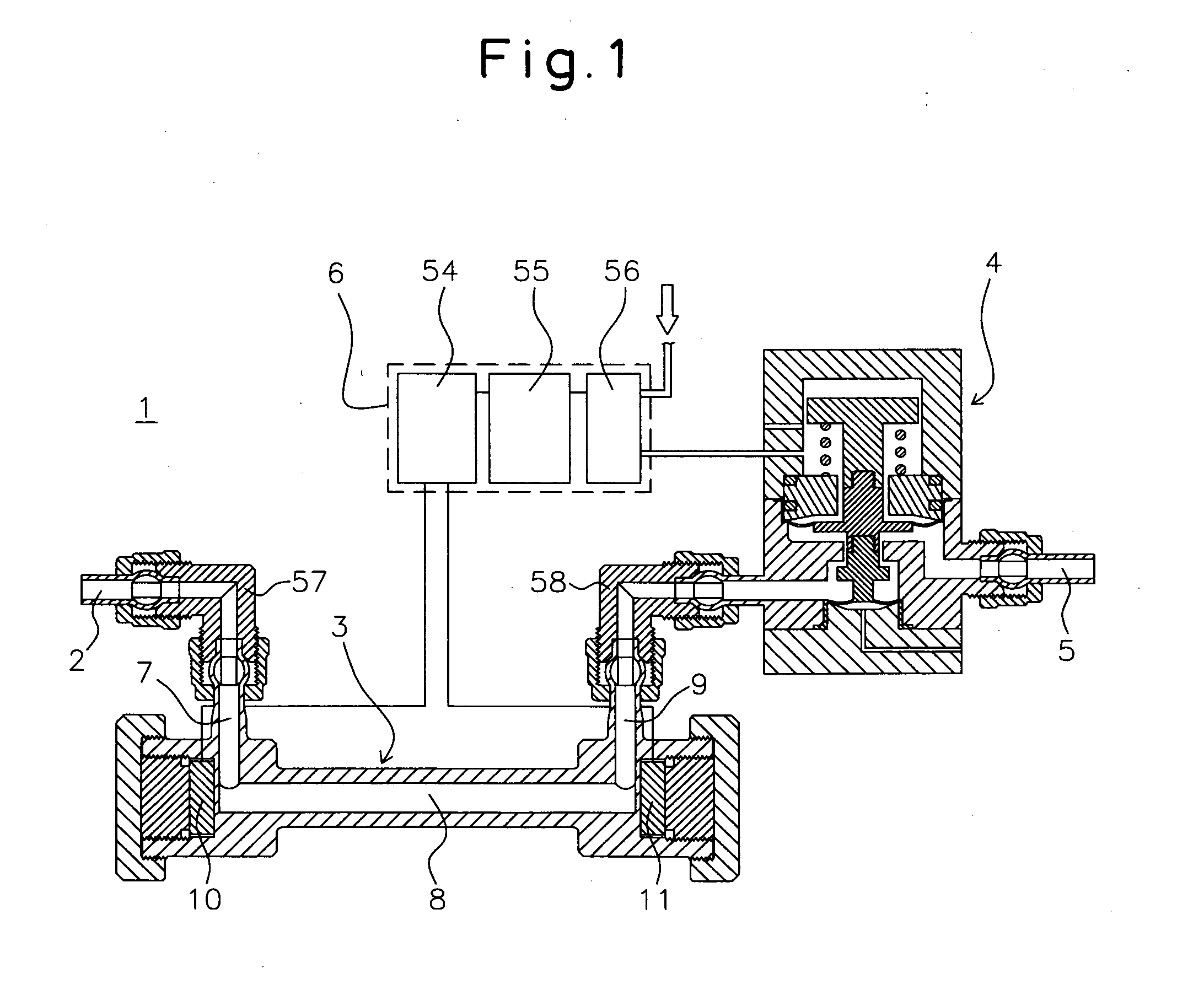
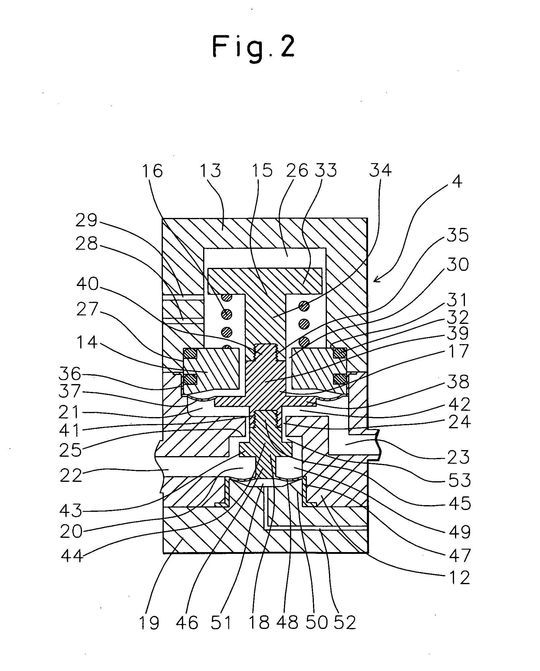
[0065]Below, a fluid control system of a first embodiment of the present invention will be explained with reference to FIG. 1 and FIG. 2.
[0066]1 is a fluid control system installed in a semiconductor production facility performing an etching process in the production of semiconductors. The fluid control system 1 is formed from a fluid inflow port 2, flow rate measuring device 3, fluid control valve 4, fluid outflow port 5, and control part 6. These are configured as follows:
[0067]2 is a PFA fluid inflow port. The fluid inflow port 2 is communicated with an inlet passage 7 of the later-mentioned flow rate measuring device 3.
[0068]3 is a flow rate measuring device for measuring the flow rate of a fluid. The flow rate measuring device 3 has an inlet passage 7, a straight passage 8 provided vertical from the inlet passage 7, and an outlet passage 9 provided vertical from the straight passage 8 and provided in parallel to the inlet passage 7 in the same direction. Ultrasonic oscillators ...
second embodiment
[0089]Next, a fluid control system of a second embodiment of the present invention will be explained with reference to FIG. 3 and FIG. 4.
[0090]59 is a fluid control system. The fluid control system 59 is formed from a fluid inflow port 60, shutoff valve 61, flow rate measuring device 62, fluid control valve 63, fluid outflow port 64, and control part 65. These parts are configured as follows:
[0091]61 is a shutoff valve. The shutoff valve 61 is formed from a main body 66, a drive unit 67, a piston 68, a diaphragm holder 69, and a valve element 70.
[0092]66 is a PTFE main body. It has a valve chamber 71 at the center of the top end in the axial direction and an inlet passage 72 and outlet passage 73 communicating with the valve chamber 71. The inlet passage 72 communicates with the fluid inflow port 60, while the outlet passage 73 communicates with the flow rate measuring device 62. Further, at the outer side of the valve chamber 71 at the top face of the main body 66, a ring-shaped gr...
third embodiment
[0103]Next, a fluid control system of a third embodiment of the present invention will be explained with reference to FIG. 5 to FIG. 9.
[0104]81 is a fluid control system. The fluid control system 81 is formed from a fluid inflow port 82, flow rate measuring device 83, fluid control valve 84, throttle valve 85, fluid outflow port 86, and control part 87. These are configured as follows:
[0105]85 is a throttle valve with an adjustable opening area. The throttle valve 85 is formed from a main body 88, diaphragm 97, second stem 106, diaphragm holder 108, first stem 114, first stem support member 121, and bonnet 125.
[0106]88 is a PTFE main body. At the top of the main body 88, it has a substantially dish-shaped valve chamber 90 formed with a later explained diaphragm 97. At the bottom face of the valve chamber 90, a valve seat face 89 fully closing and sealing the passage by being pressed against by a later explained second valve element 99 is formed. This also has an inlet passage 92 com...
PUM
 Abstract
Description
Claims
Application Information
 - R&D
- Intellectual Property
- Life Sciences
- Materials
- Tech Scout
- Unparalleled Data Quality
- Higher Quality Content
- 60% Fewer Hallucinations
Browse by: Latest US Patents, China's latest patents, Technical Efficacy Thesaurus, Application Domain, Technology Topic, Popular Technical Reports.
© 2025 PatSnap. All rights reserved.Legal|Privacy policy|Modern Slavery Act Transparency Statement|Sitemap|About US| Contact US: help@patsnap.com


