Fluorescence detecting method

Active Publication Date: 2009-11-19
FUJIFILM CORP
View PDF0 Cites 10 Cited by
  • Summary
  • Abstract
  • Description
  • Claims
  • Application Information

AI Technical Summary

Benefits of technology

[0027]The fluorescence detecting method of the present invention detects fluorescence with the plurality of fine metallic particles dispersed on the detecting portion. Thereby, the hot spots which are generated in the gaps among the fine metal particles or the gaps among the fine metal particles and the metal film can enhance the fluorescence generated by the fluorescent labels which are present within the hot spots. The plurality of fine metal particles are widely dispersed on the detecting portion. Therefore, the hot spots are formed over a wide range. As a result, a fluorescence detecting method which is more simple and realized as a

Problems solved by technology

Therefore, although Raman spectroscopy is effective for qualitative analysis, expectations cannot be held regarding the quant

Method used


Image

  • Fluorescence detecting method
  • Fluorescence detecting method
  • Fluorescence detecting method

Examples


Example

First Embodiment

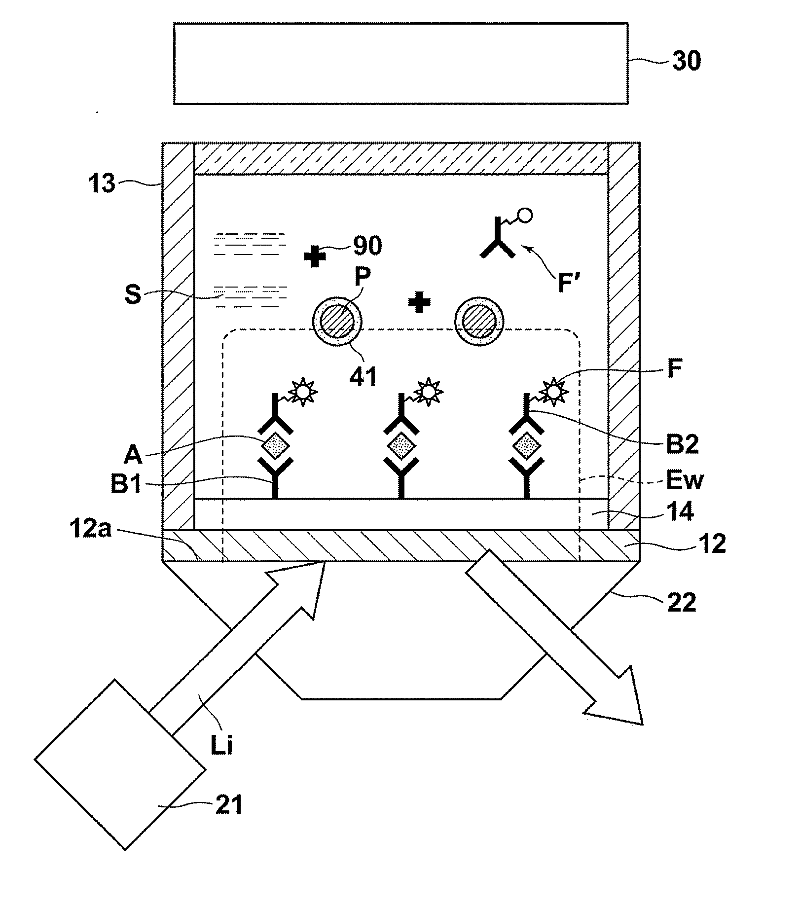
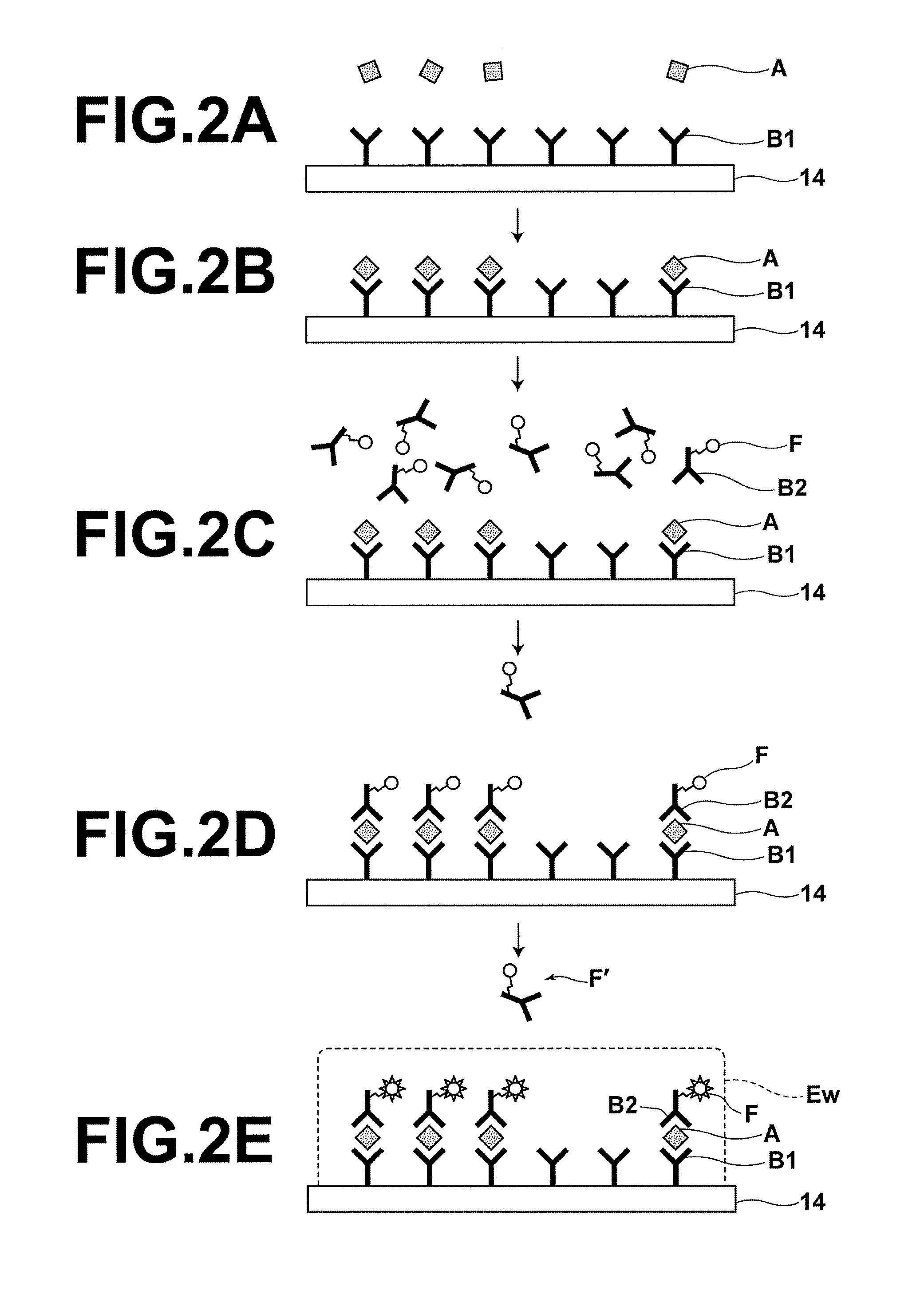
[0040]FIG. 1 is a schematic sectional diagram that illustrates a fluorescence detecting apparatus that executes the fluorescence detecting method of the present invention. In the first embodiment, a case will be described in which an antigen A is detected as a detection target substance from a sample S that contains the antigen A.

[0041]As illustrated in FIG. 1, the fluorescence sensor is equipped with: a light source 21 that emits an excitation light beam Li of a predetermined wavelength; a dielectric prism substrate 22 formed by a material that transmits the excitation light beam Li, provided to cause the excitation light beam Li to propagate therethrough from a first side thereof; a metal film 12, provided on a second side of the dielectric prism substrate 22; a non flexible film 14 which is formed on the metal film 12; primary antibodies which are immobilized onto the non flexible film 14 and that specifically bind with the antigens A; a sample holding section 13...

Example

Second Embodiment

[0084]FIG. 4 is a schematic sectional diagram that illustrates the vicinity of a detecting portion, on which fine metallic particles P are dispersed, in a fluorescence detecting apparatus that executes a fluorescence detecting method according to a second embodiment of the present invention. The fluorescence detecting apparatus which is utilized in the second embodiment is the same as that which is illustrated in FIG. 1 and was described as the first embodiment. Meanwhile, the fluorescence detecting method according to the second embodiment differs from the fluorescence detecting method according to the first embodiment in that the wavelength of the excitation light beam Li is a specific wavelength which is capable of inducing localized plasmon in the fine metallic particles P. For this reason, the elements of the fluorescence detecting apparatuses are the same, and detailed descriptions of the elements will be omitted insofar as they are not particularly necessary...

Example

Third Embodiment

[0091]FIG. 5 is a schematic sectional diagram that illustrates the vicinity of a detecting portion, on which fine metallic particles P are dispersed, in a fluorescence detecting apparatus that executes a fluorescence detecting method according to a third embodiment of the present invention. The fluorescence detecting apparatus which is utilized in the third embodiment is the same as that which is illustrated in FIG. 1 and was described as the first embodiment. However, the fluorescence detecting method of the third embodiment differs from the fluorescence detecting method of the first embodiment, in that fluorescent labels which are used to label a detection target substance are constituted by an anti quenching fluorescent material, in which fluorescent pigment molecules are enveloped in an anti quenching material that transmits fluorescence generated by the fluorescent pigment molecules and prevents metallic quenching, and in that the dielectric layers 41 that cove...


PUM


Abstract

A fluorescence detecting method utilizes surface plasmon enhancement. An electric field enhancing field is caused to be generated at a detecting portion that includes a metal film provided on a surface of a dielectric prism. Fluorescence emitted by fluorescent labels, which are attached to a detection target substance, due to the excitation effect of the electric field enhancing field is detected by a photodetector. During the detection, a plurality of fine metal particles are dispersed on the detecting portion.

Description

BACKGROUND OF THE INVENTION[0001]1. Field of the Invention[0002]The present invention is related to a fluorescence detecting method. More particularly, the present invention is related to a fluorescence detecting method that utilizes surface plasmon.[0003]2. Description of the Related Art[0004]Fluorometry is conventionally used in for biological measurements and the like, as an easy and highly sensitive measuring method. In fluorometry, a sample, which is considered to contain a detection target substance that emits fluorescence when excited by light having a specific wavelength, is irradiated with an excitation light beam of the aforementioned specific wavelength. The presence of the detection target substance can be confirmed by detecting the fluorescence due to the excitation. In the case that the detection target substance is not a fluorescent substance, a substance labeled by a fluorescent substance that specifically bonds with the detection target substance is caused to contac...

Claims


Application Information

Patent Timeline
IPC IPC(8): G01J1/58
CPCG01N21/6428G01N21/648G01N33/582G01N33/54373G01N33/54346
Inventor OHTSUKA, HISASHI
Owner FUJIFILM CORP
Why Eureka
Try Eureka