Particle beam irradiation system

a particle beam and irradiation system technology, applied in the field of particle beam irradiation system, can solve the problems of complicated control device configuration, difficult to extract an ion beam having a desired intensity, complicated adjustment, etc., and achieve the effect of accurately controlling the intensity of an ion beam and accurately controlling the outgoing beam intensity

Active Publication Date: 2009-11-19
HITACHI LTD
View PDF14 Cites 106 Cited by
  • Summary
  • Abstract
  • Description
  • Claims
  • Application Information

AI Technical Summary

Benefits of technology

[0017]It is an object of the present invention to provide a charged particle beam extraction method and particle beam irradiation system that make it possible to exercise intensity control over an extracted ion beam while a simple device configuration is employed.
[0020]The present invention makes it possible not only to accurately control the outgoing beam intensity in accordance with the accumulated amount of ion beam that moves circularly within the synchrotron, but also to accurately control the intensity of an ion beam that falls on a radiation target.

Problems solved by technology

Therefore, it is not easy to extract an ion beam having a desired intensity.
This complicates the adjustment for causing the estimation result to match the intensity control result of an actually extracted ion beam.
Consequently, the resulting control device configuration is complicated.

Method used


Image

  • Particle beam irradiation system
  • Particle beam irradiation system
  • Particle beam irradiation system

Examples


first embodiment

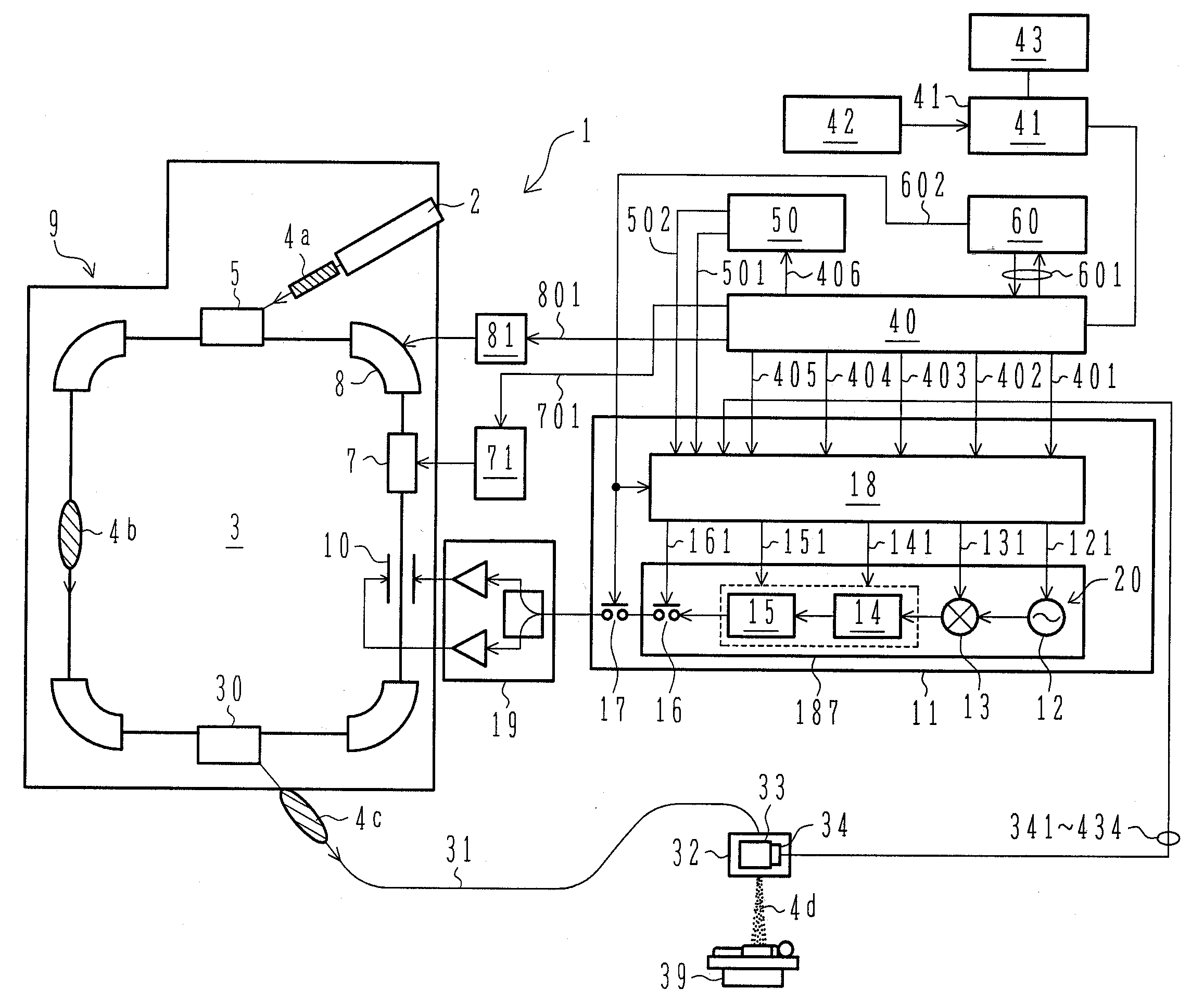
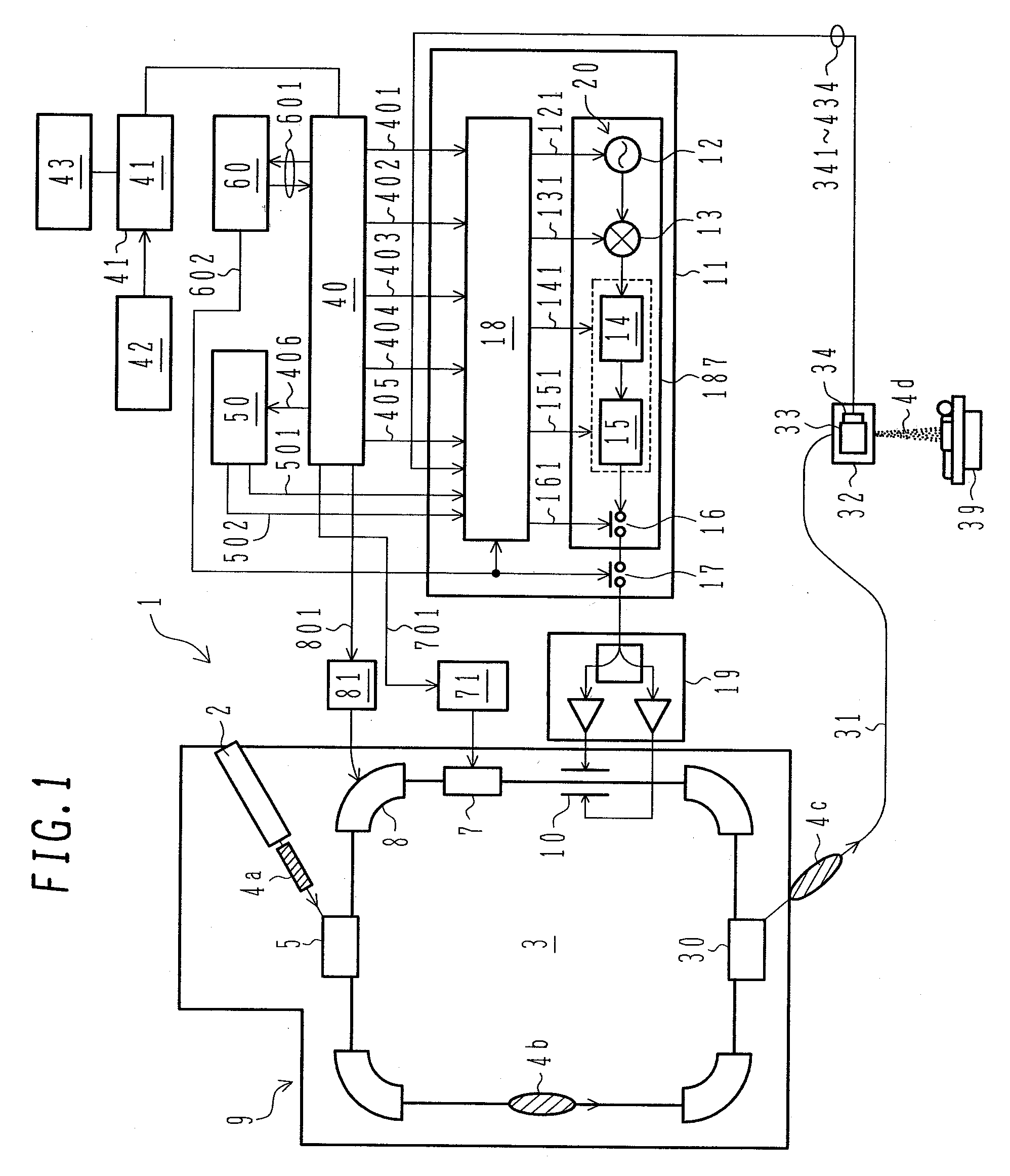
[0035]A particle beam therapy system according to a first embodiment of the present invention will now be described with reference to FIGS. 1 and 7. As shown in FIG. 1, the particle beam therapy system 1 according to the present embodiment includes an ion beam generator 9, a beam transport apparatus 31, and an irradiation field formation apparatus (charged particle beam irradiation apparatus; hereinafter referred to as the irradiation apparatus) 32. The beam transport apparatus 31 provides communication between the ion beam generator 9 and the irradiation apparatus 32, which is installed in a therapy room.

[0036]The ion beam generator 9 includes an ion source (not shown), a preaccelerator 2, and a synchrotron 3. The ion source is connected to the preaccelerator 2. The synchrotron 3 is configured so that an injector 5, a radiofrequency accelerator (acceleration cavity) 7, a plurality of bending magnets 8, a plurality of quadrupole magnets (not shown), a radiofrequency electrode (radio...

second embodiment

[0079]A particle beam therapy system according to a second embodiment of the present invention will now be described. The particle beam therapy system according to the present embodiment is configured so that the irradiation apparatus 32 of the particle beam therapy system 1 according to the first embodiment is replaced with an irradiation apparatus 32A for use with a scanning irradiation method. The irradiation apparatus 32A is obtained by removing the RMW 33 and rotation detector 34 from and adding a scanning magnet (not shown) to the irradiation apparatus 32. An extraction control apparatus 11A according to the present embodiment is obtained by removing the multiplier circuit 182 and AND circuit 183 from and adding a control logic device 185a to the extraction control apparatus 11 according to the first embodiment. The control logic device 185a is connected to the control processor for extraction 180 and the radiofrequency switch 16.

[0080]The scanning irradiation method according...

third embodiment

[0090]A particle beam therapy system according to a third embodiment of the present invention will now be described. The particle beam therapy system according to the present embodiment is configured similar to the particle beam therapy system according to the first embodiment. As shown in FIG. 5-(e), the control signal output unit 181c according to the first embodiment outputs the local modulation signal 151 that does not vary with time during the irradiation period (Tb). However, the control signal output unit 181c according to the present embodiment outputs the local modulation signal 151 that varies with time during the irradiation period (Tb), as shown in FIG. 10. The local modulation signal 151 controls the intensity of the ion beam extracted from the synchrotron 3 in accordance with the rotation angle of the RMW 33. When the local modulation signal 151 is varied in accordance with the rotation angle of the RMW 33 as described in conjunction with the present embodiment, the in...


PUM


Abstract

It is an object of the present invention to provide a charged particle beam extraction method and particle beam irradiation system that make it possible to exercise intensity control over an extracted ion beam while a simple device configuration is employed. To accomplish the above object, there is provided a particle beam irradiation system comprising: a synchrotron for accelerating and extracting an charged particle beam; an irradiation apparatus for extracting the charged particle beam that is extracted from the synchrotron; first beam intensity modulation means for controlling the beam intensity of the charged particle beam extracted from the synchrotron during an extraction control period of an operation cycle of the synchrotron; and second beam intensity modulation means for controlling the beam intensity during each of a plurality of irradiation periods contained in the extraction control period of the operation cycle.

Description

CROSS-REFERENCES[0001]This is a divisional of U.S. Ser. No. 11 / 692,331, filed Mar. 28, 2007, the entire disclosure of the above-identified application is incorporated herewith.BACKGROUND OF THE INVENTION[0002]1. Field of the Invention[0003]The present invention relates to a particle beam irradiation system, and more particularly to a particle beam irradiation system that is suitably applicable to a particle beam therapy system, which provides cancer treatment by irradiating a diseased part with a proton, heavy ion, or other charged particle beam.[0004]2. Description of the Related Art[0005]Particle beam therapy is known as radiological therapy of cancer. In particle beam therapy, a patient's cancerous part is irradiated with a proton, heavy ion, or other ion beam for therapy purposes. A particle beam therapy system that provides particle beam therapy includes an ion beam generator, a beam transport line, and an irradiation apparatus. The ion beam generator includes a synchrotron or ...

Claims


Application Information

Patent Timeline
Patent Type & Authority Applications(United States)
IPC IPC(8): A61N5/00
CPCA61N5/1043A61N2005/1087H05H7/10G21K5/04G21K1/10
Inventor NISHIUCHI, HIDEAKISAITO, KAZUYOSHI
Owner HITACHI LTD
Why Eureka
Try Eureka