Method for electrostatic coating of a medical device

a medical device and electrostatic coating technology, applied in the field of electrostatic coating a medical device, can solve the problems of wasting a large amount of coating material, affecting the safety of operators and the environment, and hazardous for the operator and the environment, and achieve the effect of reducing the risk of contamination, and reducing the safety of users

Active Publication Date: 2009-11-19
ABBOTT CARDIOVASCULAR
View PDF7 Cites 112 Cited by
  • Summary
  • Abstract
  • Description
  • Claims
  • Application Information

AI Technical Summary

Problems solved by technology

Problems with PTCA include formation of intimal flaps or torn arterial linings, both of which can create another occlusion in the lumen of the coronary artery.
Moreover, thrombosis and restenosis may occur several months after the procedure and create a need for additional angioplasty or a surgical by-pass operation.
However, dipping and spraying techniques requires for large amounts of drugs and solvents to be used which can be hazardous for the operator and the environment.
The current dipping and spray techniques are very wasteful methods of coating medical devices, most particularly when very small geometrical structures like stents are being coated.
For example, during the spray application of the drug composition, a majority of the coating material, including a drug, is wasted as only a fraction of the spray flux is intercepted by the stent struts.
Moreover, dipping and spray coating processes can tend to promote a great deal of coating defects.
Coating defects can include an uneven thickness in stent and balloon coating, which would in effect translate into uneven distribution of the drug across the surface body of the medical device.
Stent coating defects can also include “webbing” between stent struts (over the gaps or opening between the struts) or coating “pools” which are excessive gatherings

Method used


Image

  • Method for electrostatic coating of a medical device
  • Method for electrostatic coating of a medical device

Examples


Embodiment Construction

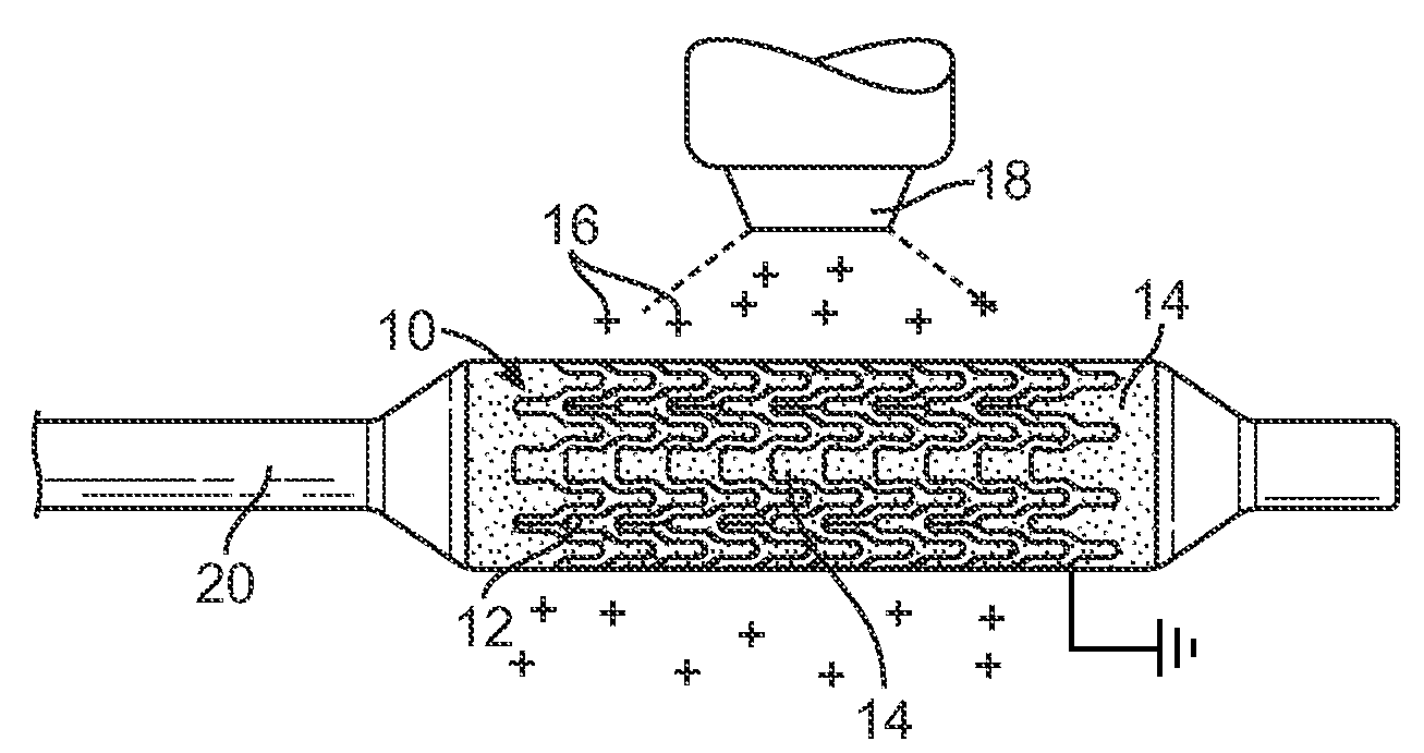
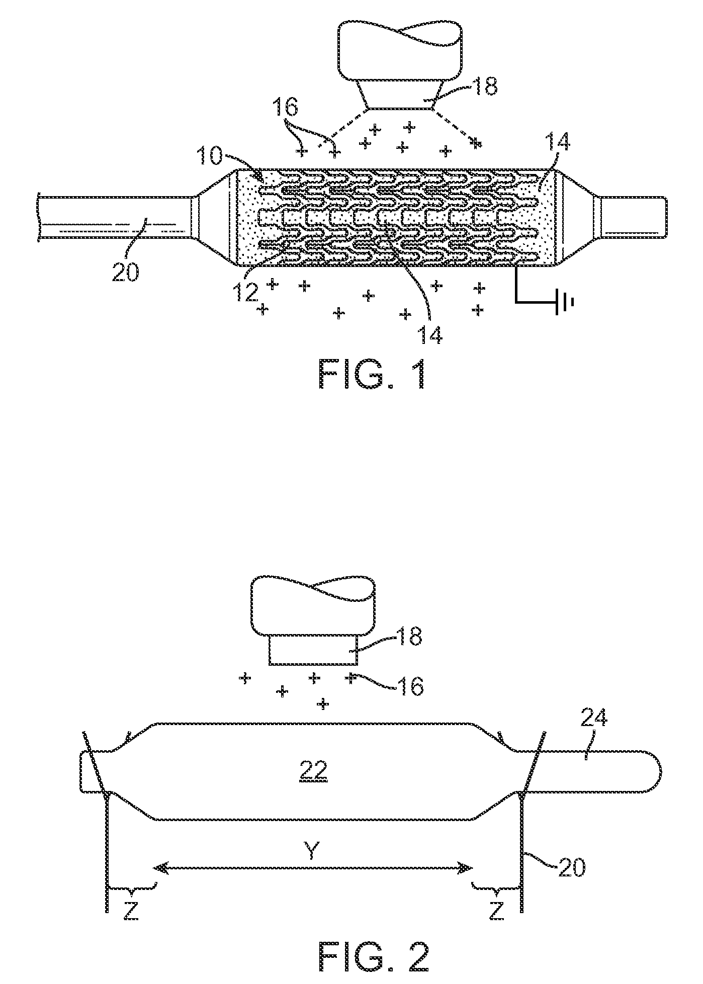
[0022]A method is provided for electrostatically coating stents having a polymeric component. As illustrated in FIG. 1, a stent 10 is supported by a mandrel or support structure 20. The mandrel or support structure 20 can be coupled to a driving means to provide rotational motion for spinning the stent 10 during electrostatic deposition. In one embodiment, the stent 10 can have a hollow, tubular body, including struts separated by gaps, as best illustrated by reference number 12 and 14, respectively. In other embodiments, the stent can be made from wires, fibers, coiled sheet, with or without gaps, or a scaffolding network of rings connected by arms. The stent can have any particular geometrical configuration, such as sinusoidal strut configuration, and should not be limited to what is illustrated in FIG. 1. The stent can be balloon expandable or self-expandable, both of which are well known in the art. The stent is preferably for cardiovascular use. In some embodiments, the stent c...


PUM

PropertyMeasurementUnit
Timeaaaaaaaaaa
Timeaaaaaaaaaa
Timeaaaaaaaaaa

Abstract

A method for electrostatic coating of medical devices such as stents and balloons is described. The method includes applying a composition to a polymeric component of a medical device which has little or no conductivity. The polymeric component could be a material from which the body or a strut of the stent is made or could be a polymeric coating pre-applied on the stent. The polymeric component could be the balloon wall. A charge can then be applied to the polymeric component or the polymeric component can be grounded. Charged particles of drugs, polymers, biobeneficial agents, or any combination of these can then be electrostatically deposited on the medical device or the coating on the medical device. One example of the composition is iodine, iodine, iodide, iodate, a complex or salt thereof which can also impart imaging capabilities to the medical device.

Description

CROSS REFERENCE[0001]This application is a continuation-in-part of U.S. application Ser. No. 12 / 121,692, filed on May 15, 2008, the entire content of which is incorporated by reference.FIELD OF INVENTION[0002]The present invention is related to methods of electrostatically coating a medical device, more specifically a stent or a balloon. More particularly, the present invention is related to methods of electrostatically depositing drugs or active agents on polymeric stents, polymeric coatings on stents, polymeric dilatation balloons, or other medical devices.BACKGROUND OF THE INVENTION[0003]In percutaneous transluminal coronary angioplasty (PTCA), a balloon catheter is inserted through a brachial or femoral artery, positioned across a coronary artery occlusion, and inflated to compress against atherosclerotic plaque to open, by remodeling, the lumen of the coronary artery. The balloon is then deflated and withdrawn. Problems with PTCA include formation of intimal flaps or torn arter...

Claims


Application Information

Patent Timeline
IPC IPC(8): B05D3/00
CPCA61L31/14A61L31/16A61L2300/416B05D1/007A61L2420/02A61L31/08A61L2300/606
Inventor KERRIGAN, CAMERON K.PACETTI, STEPHEN
Owner ABBOTT CARDIOVASCULAR
Why Eureka
Try Eureka