Solid polymer electrolytic fuel cell

Active Publication Date: 2009-11-19
PANASONIC CORP
View PDF8 Cites 55 Cited by
  • Summary
  • Abstract
  • Description
  • Claims
  • Application Information

AI Technical Summary

Benefits of technology

[0040]In accordance with the above-mentioned structure, for example, the anode-side elastic member having the frame shape on the plan view and the cathode-side elastic member having the frame shape on the plan view are placed on the edge portion inside the frame member supporting the polymer electrolyte membrane and the like, and each of the elastic members is allowed to have the length equal to or longer than the gap dimension between the membrane-electrode-frame assembly and the separator in the assembled state of the single cell modules, with the elastic member being elastically deformed in a thickness direction of the membrane-electrode-frame assembly in the assembled state of the single cell modules, so that the gap between the membrane-electrode-frame assembly and the separator is sealed in a tightly contact state. With this arrangement, the anode-side elastic member is elastically deformed between the frame member and the anode-side separator at the time of assembling the single cells so that the elastically deformed anode-side elastic member is made in tightly contact with the gap between the frame member and the anode-side separator to seal the gap, thereby exerting a sealing effect. In the same manner, on the cathode side also, the cathode-side elastic member is elastically deformed between the frame member and the cathode-side separator at the time of assembling the single cells so that the elastically deformed cathode-side elastic member is made in tightly contact with the gap between the frame member and the cathode-side separator to seal the gap, thereby exerting a sealing effect.
[0041]As a result, by the elastically deformed anode-side elastic member and the elastically deformed cathode-side elastic member, the gaps between the frame member and the anode-side separator as well as between the frame member and the cathode-side separator are respectively sealed in a tightly contact state so that it becomes possible to effectively restrain a cross-leak phenomenon occurring through the gap between the polymer electrolyte membrane and the frame, and also to respectively restrain a short-circuiting flow of a reducing agent gas along the edge portion of the frame member and a short-circuiting flow of an oxidizing agent gas along the edge portion of the frame member, thereby making it possible to further improve the utilization rates of the reducing agent gas and the oxidizing agent gas, and consequently to further improve the performances of

Problems solved by technology

However, the above-mentioned joining methods for the polymer electrolyte membrane by the use of thermal compression bonding or a bonding agent tend to cause degradation in performances of the polymer electrolyte membrane due to heat and volatile components of the bonding agent, and the application conditions are consequently limited.
Moreover, the joining method by the use of mechanical cramping causes an issue in that cross-leak easily occurs through a fine gap between the polymer electrolyte membrane and the frame member.
Moreover

Method used


Image

  • Solid polymer electrolytic fuel cell
  • Solid polymer electrolytic fuel cell
  • Solid polymer electrolytic fuel cell

Examples


first embodiment

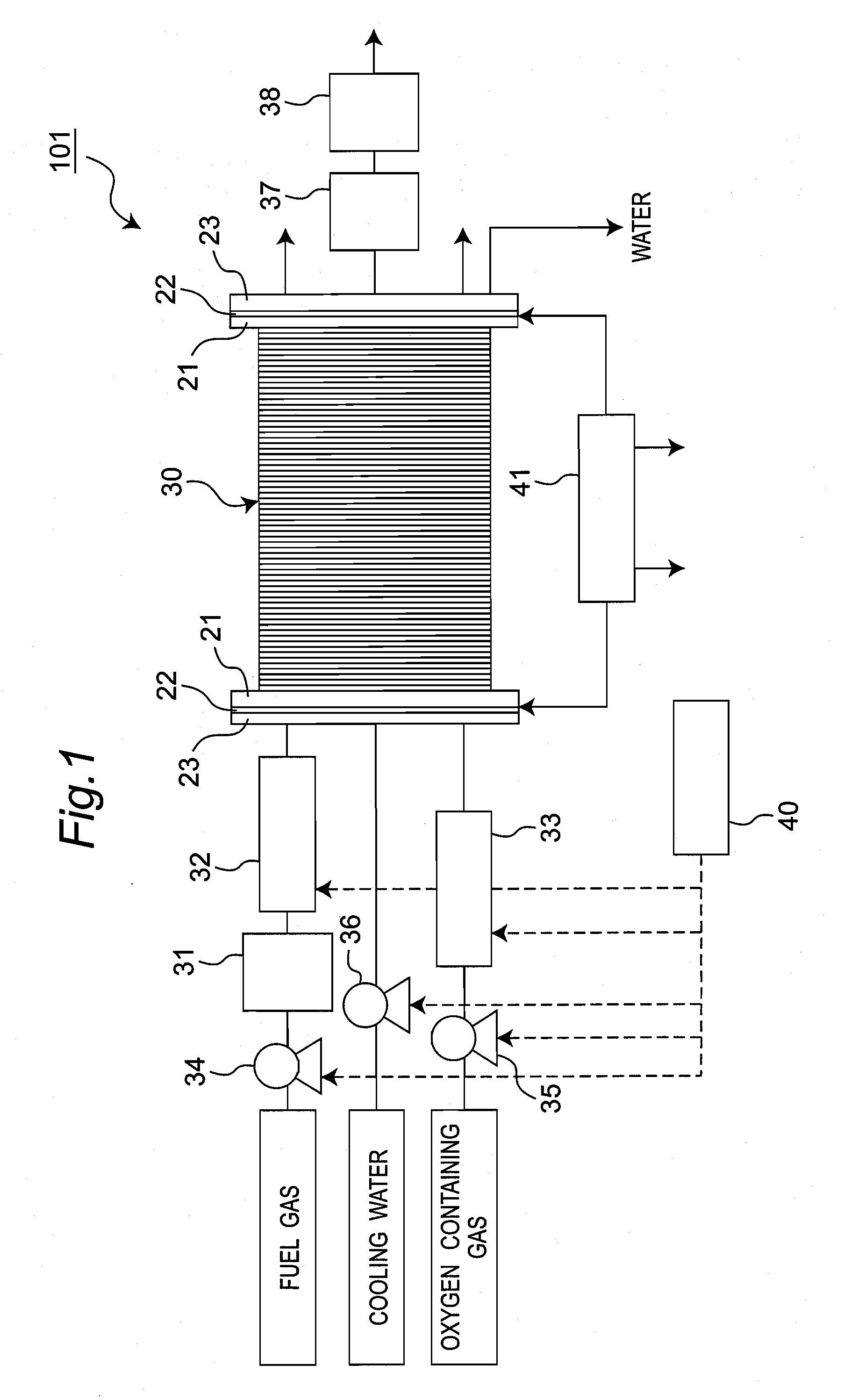
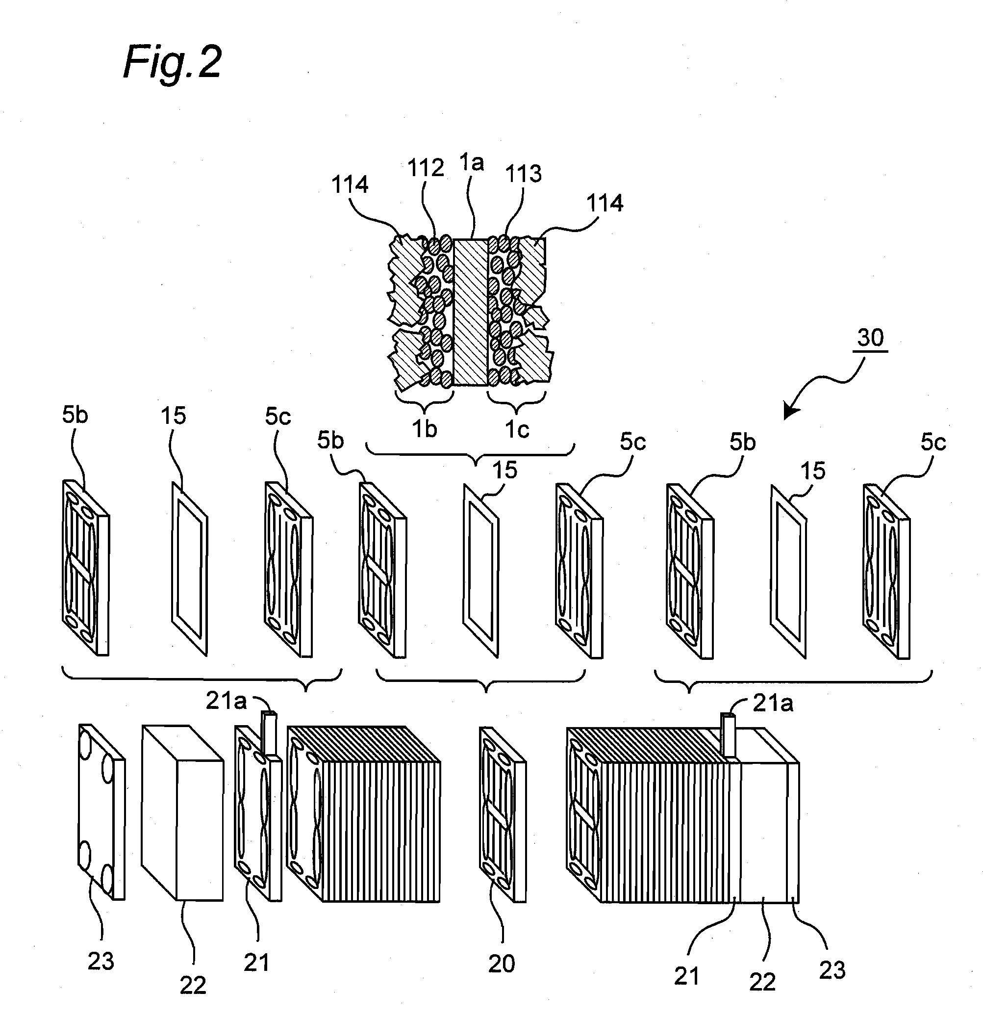
[0104]FIG. 1 is a schematic constitution view that schematically shows a structure of a fuel cell provided with a stack for a fuel cell in accordance with one embodiment of the present invention. Moreover, FIG. 2 is a schematic exploded view that shows a stack for a fuel cell possessed by the fuel cell 101 shown in FIG. 1 (hereinafter, referred to as stack).

[0105]The fuel cell 101, which is, for example, a solid polymer electrolytic fuel cell (PEFC), is designed to generate electric power, heat, and water simultaneously, by allowing a fuel gas containing hydrogen and an oxidizing agent gas containing oxygen such as air to react with each other electrochemically. As shown in FIG. 1, the fuel cell 101 is provided with a stack 30 having a laminated structure in which a plurality of fuel cells (or a single cell), each having a pair of anode and cathode electrodes, are series-connected with one another, a fuel processing device 31 for taking out hydrogen from a fuel gas, an anode humidif...

second embodiment

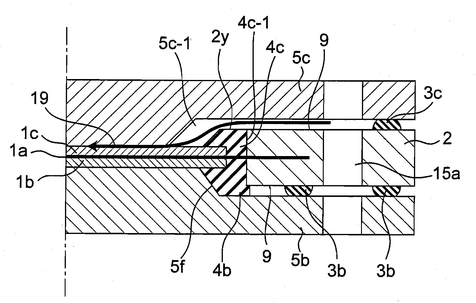
[0133]FIG. 5A is a schematic cross-sectional view that schematically shows a structure of single cells of a fuel cell provided with a stack for a fuel cell in accordance with a second embodiment of the present invention.

[0134]In the second embodiment, the aforementioned single cell of the first embodiment is designed in such a manner that the inclined surface 5f of the anode-side separator 5b and the inclined surface 5g of the cathode-side separator 5c are not formed into an entirely circumferential frame shape on the plan view, but formed as a partial portion. Moreover, in the first embodiment, the anode-side inclined surface and the cathode-side inclined surface of the elastic members 4b and 4c are prepared as the bottom surface of the anode-side concave section 4f and the bottom surface of the cathode-side concave section 4g; however, not limited by this structure, these may be prepared as the surface of the anode-side rib 4d and the surface of the cathode-side rib 4e. Furthermor...

modified examples

[0136]The present invention is not intended to be limited by the above-mentioned embodiments, and various modified modes may be carried out.

[0137]For example, in the polymer electrolyte membrane 1a of each of the embodiments, in addition to the integrally-molded structure by using the elastic members 4b and 4c, one more reinforcing membrane 13 (see FIGS. 5A and 5B) may be placed to protect the anode electrode 1b and the cathode electrode 1c, and the same effects can be obtained.

[0138]Moreover, another modified example may be used in which in each of the embodiments, at portions where the anode-side elastic member 4b and the cathode-side elastic member 4c are placed, since the same sealing effect for gases as that of the gaskets 3b and 3c is obtained by the elastically deforming effect thereof, the reducing agent gas 11a and the oxidizing agent gas 11b are respectively sealed so that no gaskets 3b and 3c are required on the outer circumferential portion.

[0139]Still another modified e...


PUM


Abstract

Elastic members that are integrally joined to a frame member are placed between an outer edge of an electrode unit and an inner edge of the frame member, and in the assembled state of the single cell module, the elastic members are elastically deformed in the thickness direction of a membrane-electrode-frame assembly so that the gap between the membrane-electrode-frame assembly and the separator is sealed in a tightly contact state.

Description

TECHNICAL FIELD[0001]The present invention relates to a solid polymer electrolytic fuel cell, and more particularly to an improved sealing structure for a fuel cell between an electrolyte membrane-electrode assembly and a conductive separator.BACKGROUND ART[0002]The most typical solid polymer electrolytic fuel cell is configured by a polymer electrolyte membrane supported by a frame member having a gasket for sealing gas placed on its peripheral portion, an electrolyte membrane-electrode assembly (MEA) formed by an anode joined to one of the surfaces of the electrolyte membrane and a cathode joined to the other surface of the electrolyte membrane, and an anode-side conductive separator plate and a cathode-side conductive separator plate that sandwich the MEA, and a gas supply unit for supplying a fuel gas and an oxidizing agent gas to the anode and the cathode respectively is formed on a peripheral edge of the center portion in the separator plate, which is made in contact with the ...

Claims


Application Information

Patent Timeline
IPC IPC(8): H01M8/10H01M8/02
CPCH01M8/0273H01M8/0276Y02E60/521H01M2008/1095H01M8/1004Y02E60/50H01M8/02H01M8/24H01M8/0258H01M8/0271H01M8/242H01M8/2457H01M8/2483
Inventor MORIMOTO, TAKASHIKUSAKABE, HIROKIMATSUMOTO, TOSHIHIROKAWABATA, NORIHIKO
Owner PANASONIC CORP
Why Eureka
Try Eureka