Blowerless heat exchanger based on micro-jet entrainment

a heat exchanger and micro-jet technology, applied in the field of heat exchangers, can solve the problems of substantial reduction in flow resistance and overall power consumption, and achieve the effects of strong turbulence, slow speed, and enhanced heat transfer of electronic components

Active Publication Date: 2009-11-26
HONEYWELL INT INC
View PDF23 Cites 25 Cited by
  • Summary
  • Abstract
  • Description
  • Claims
  • Application Information

AI Technical Summary

Benefits of technology

[0009]It is a further aspect of the present invention to provide an improved heat exchanger based on micro-jet entrainment for enhanced heat transfer in electronic components.
[0010]The aforementioned aspects and other objectives and advantages can now be achieved as described herein. A blowerless heat exchanger apparatus based on micro-jet entrainment is disclosed. The heat exchanger apparatus incorporates a number of fins regularly spaced apart from each other and parallel to each other, thereby permitting airflow in a space defined therebetween. A dense array of micro-jet nozzles can be fabricated on the surface of the fins and pointing to the flow direction of the air movement in order to induce entrainment airflow. The air from an air compressor or other pressurized air sources can be utilized to deliver the primary airflow to the micro nozzles thereby creating the micro-jets with exit velocities from 100 m / s to 400 m / s. As the jets interact with the surrounding air, the momentum of the jets is transferred to a much larger air mass, resulting in the movement of the larger air mass at a slower speed (e.g. 1 m / s to 20 m / s), known as the secondary flow, which serves to carry heat away from the heatsink. In addition to the air movement, micro-jet entrainment induces strong turbulence on the fin surface, which significantly enhances heat transfer from the fin surface to the air. Thereby the entrainment heatsink could achieve low thermal resistance with less fin surface area, enabling designs that use a much larger fin spacing which leads to substantial reduction in flow resistance and overall power consumption.
[0011]The micro-jet nozzle further includes a tapered nozzle with an opening that can induce the secondary airflows, for example, in the range of 10 to 60 times of the primary flow by entrainment. Silicon-based fin structure with micro-jet nozzles can be fabricated on a silicon substrate utilizing MEMS technology. Metal-based fin structure with micro-jet nozzles can be fabricated on a stamped metal foil soldered to a metal core and micro nozzles fabricated utilizing laser micromachining process. The heat exchanger apparatus disclosed herein utilizes the air compressor to supply air to the micro-jets, which significantly reduces the size.

Problems solved by technology

Thereby the entrainment heatsink could achieve low thermal resistance with less fin surface area, enabling designs that use a much larger fin spacing which leads to substantial reduction in flow resistance and overall power consumption.

Method used


Image

  • Blowerless heat exchanger based on micro-jet entrainment
  • Blowerless heat exchanger based on micro-jet entrainment
  • Blowerless heat exchanger based on micro-jet entrainment

Examples


Embodiment Construction

[0016]The particular values and configurations discussed in these non-limiting examples can be varied and are cited merely to illustrate at least one embodiment and are not intended to limit the scope thereof.

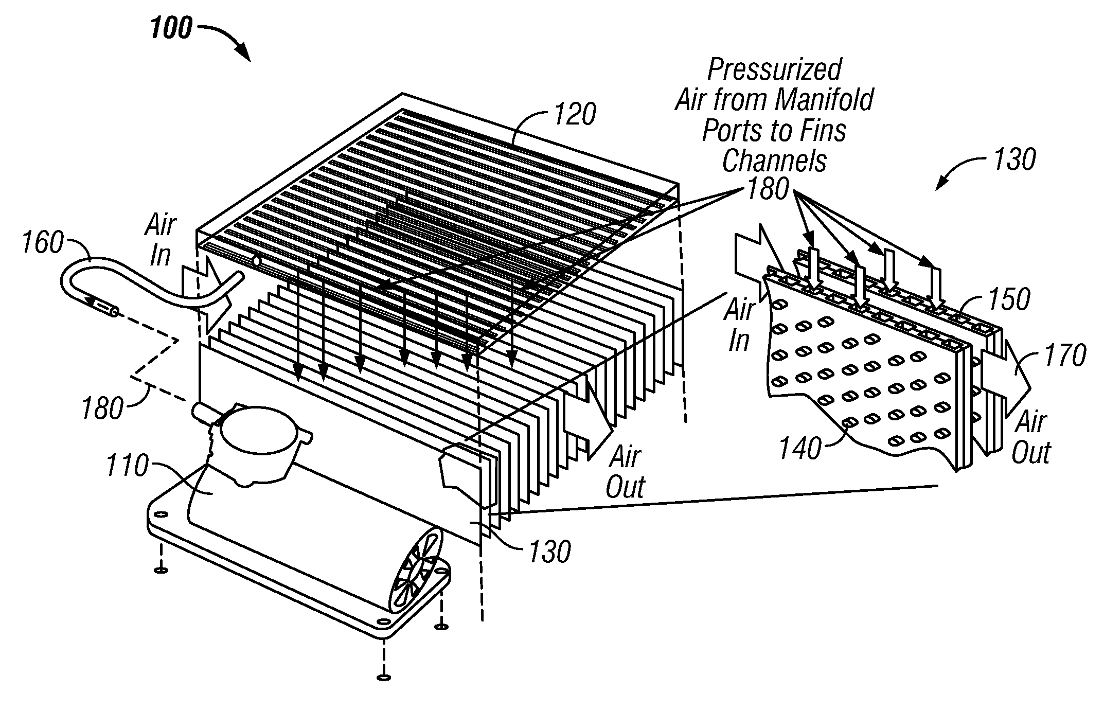
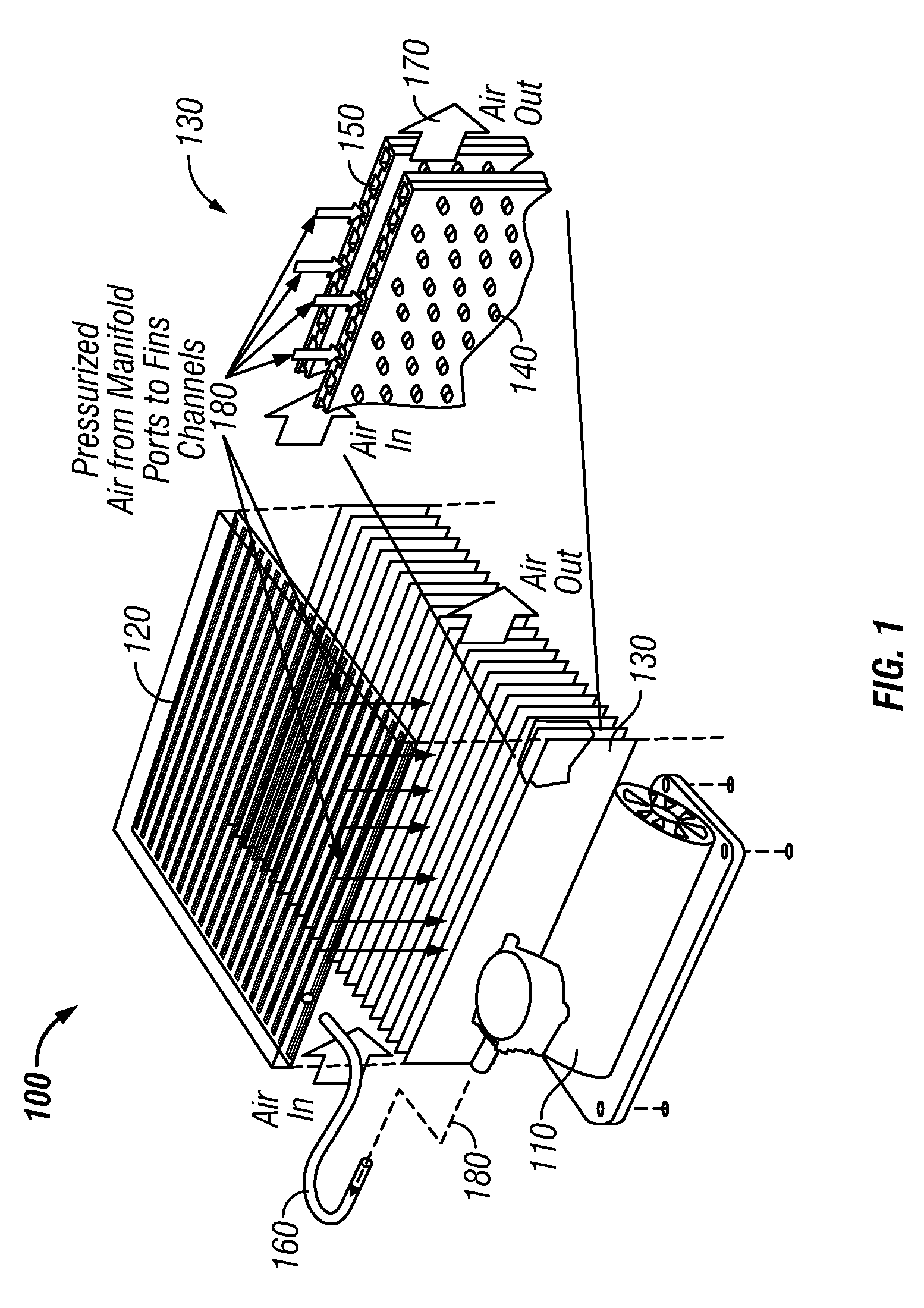
[0017]FIG. 1 illustrates an overall configuration including the main components of a heat exchanger apparatus 100, in accordance with a preferred embodiment. Apparatus 100 constitutes a blowerless heat exchanger. The apparatus 100 generally includes an air compressor 110, an air manifold 120, a number of fins 130 having a dense array of micro nozzles 140 and air delivery channels 150. The micro nozzles 140 can be fabricated in dense arrays on the surface of the fins 130, pointing to the flow direction and can induce airflow 170 by entrainment. The compressed air 180 from the compressor 110 can be passed to the manifold 120 via an air hose 160. The manifold 120 is in fluidic connection with the micro nozzles 140 via air channels 150. Therefore, the compressed air can be uniforml...


PUM

PropertyMeasurementUnit
exit velocitiesaaaaaaaaaa
speedaaaaaaaaaa
jet speedaaaaaaaaaa

Abstract

A blowerless heat exchanger apparatus based on micro-jet entrainment is disclosed. The heat exchanger apparatus incorporates a number of fins regularly spaced apart from each other and parallel to each other, thus letting air currents flow in the space defined between them. A dense array of micro-jet nozzles can be fabricated on the fins surface pointing to the flow direction of the air movement in order to induce increase airflow. The air from an air compressor delivers sufficient airflow on the fins surface utilizing micro-jets entrainment. The micro-jet entrainment confirms strong turbulent around the micro-jets and suggests significant heat transfer enhancement. The turbulence from the micro-jets enhance the heat transfer coefficient, potentially by an order of magnitude, therefore allowing much larger fin spacing and leads to huge reduction of flow resistance and overall power consumption.

Description

CROSS REFERENCE TO PROVISIONAL PATENT APPLICATION[0001]This patent application claims priority to U.S. Provisional Patent Application Ser. No. 61 / 054,544, entitled “Blowerless Heat Exchanger Based on Micro-Jet Entrainment,” which was filed on May 20, 2008, the disclosure of which is incorporated herein by reference in its entirety.TECHNICAL FIELD[0002]Embodiments are generally related to heat exchangers. Embodiments are also related to MEMS (Microelectromechanical Systems) and, more particularly, to MEMS-based structures, components and devices. Embodiments are additionally related to heat exchangers based on micro-jet entrainment.BACKGROUND OF THE INVENTION[0003]Electronic cooling has been a major impediment for system size reduction and often dictates external dimensions and form factors for computers and other equipments. Electronic systems are generally provided with a large number of heat-generating components such as, for example, microprocessors, power amplifiers, radio frequ...

Claims


Application Information

Patent Timeline
Patent Type & Authority Applications(United States)
IPC IPC(8): F28F7/00
CPCF28F3/02F28F13/12H01L23/3672H01L23/467F28F2250/08Y10T29/4935F28F2215/10H01L2924/0002F28F2215/06H01L2924/00
Inventor YANG, WEIZHANG, CHUNBOEICKHOFF, STEVEN J.GU, ALEX
Owner HONEYWELL INT INC
Why Eureka
Try Eureka