
Nano-composites for thermal barrier coatings and thermo-electric energy generators

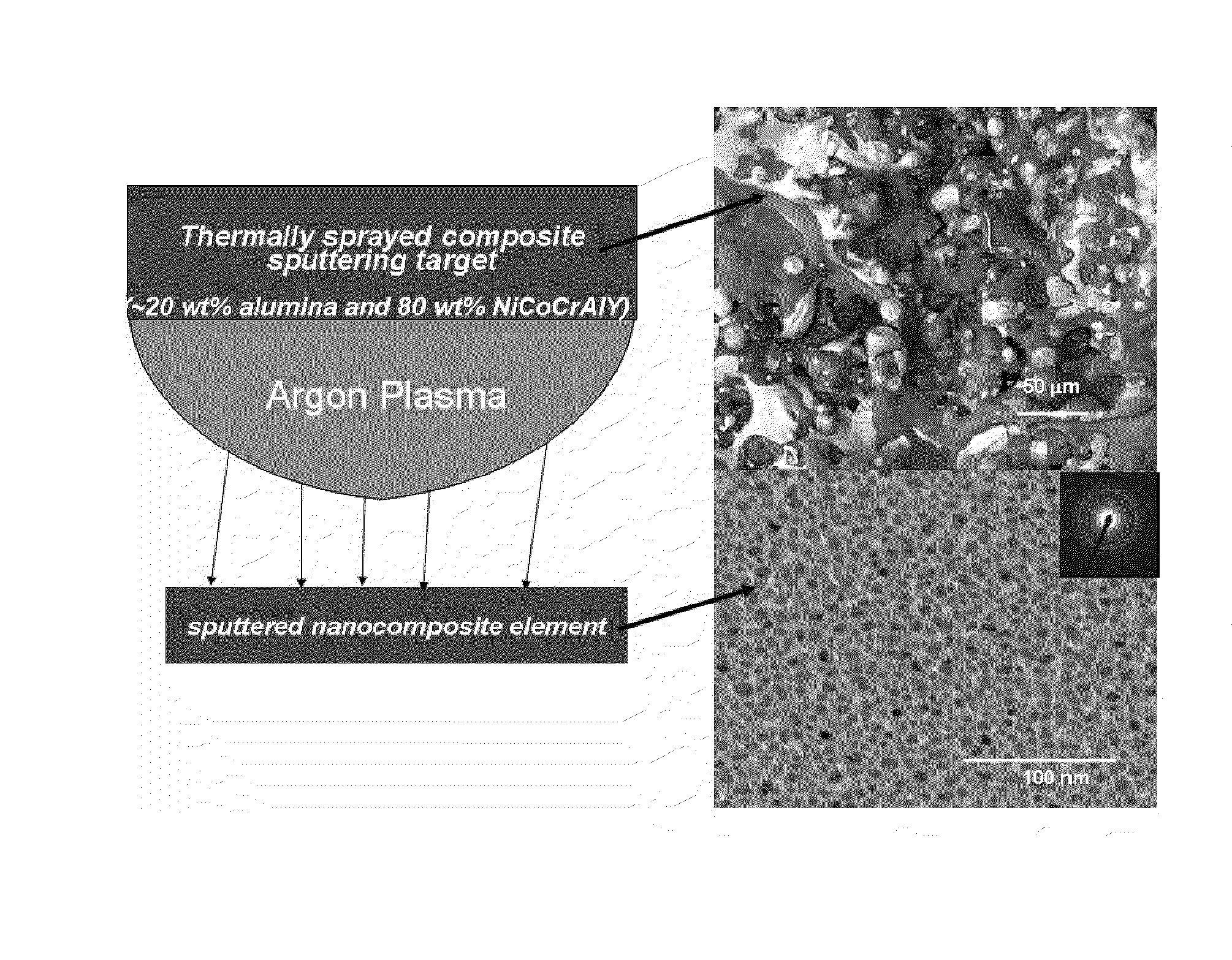
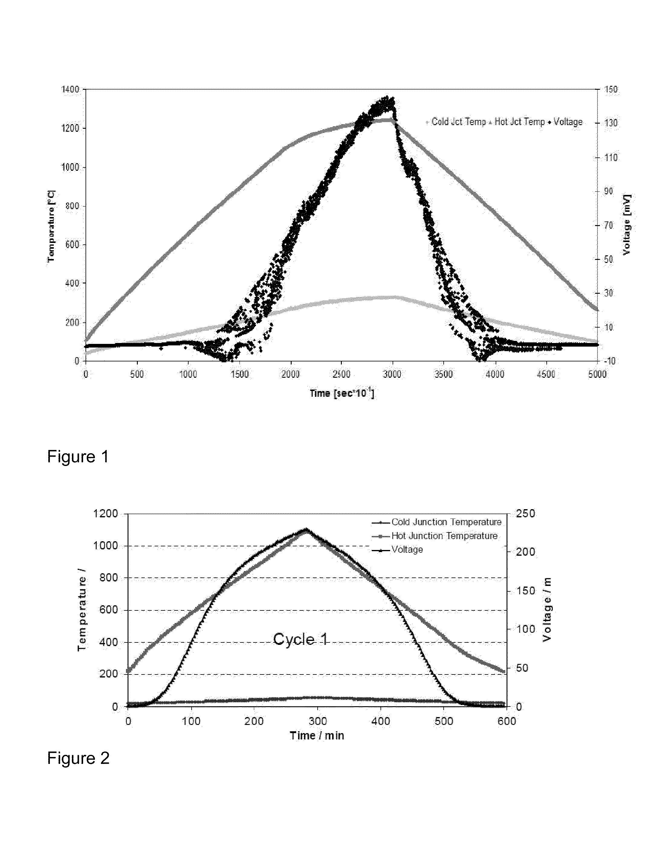
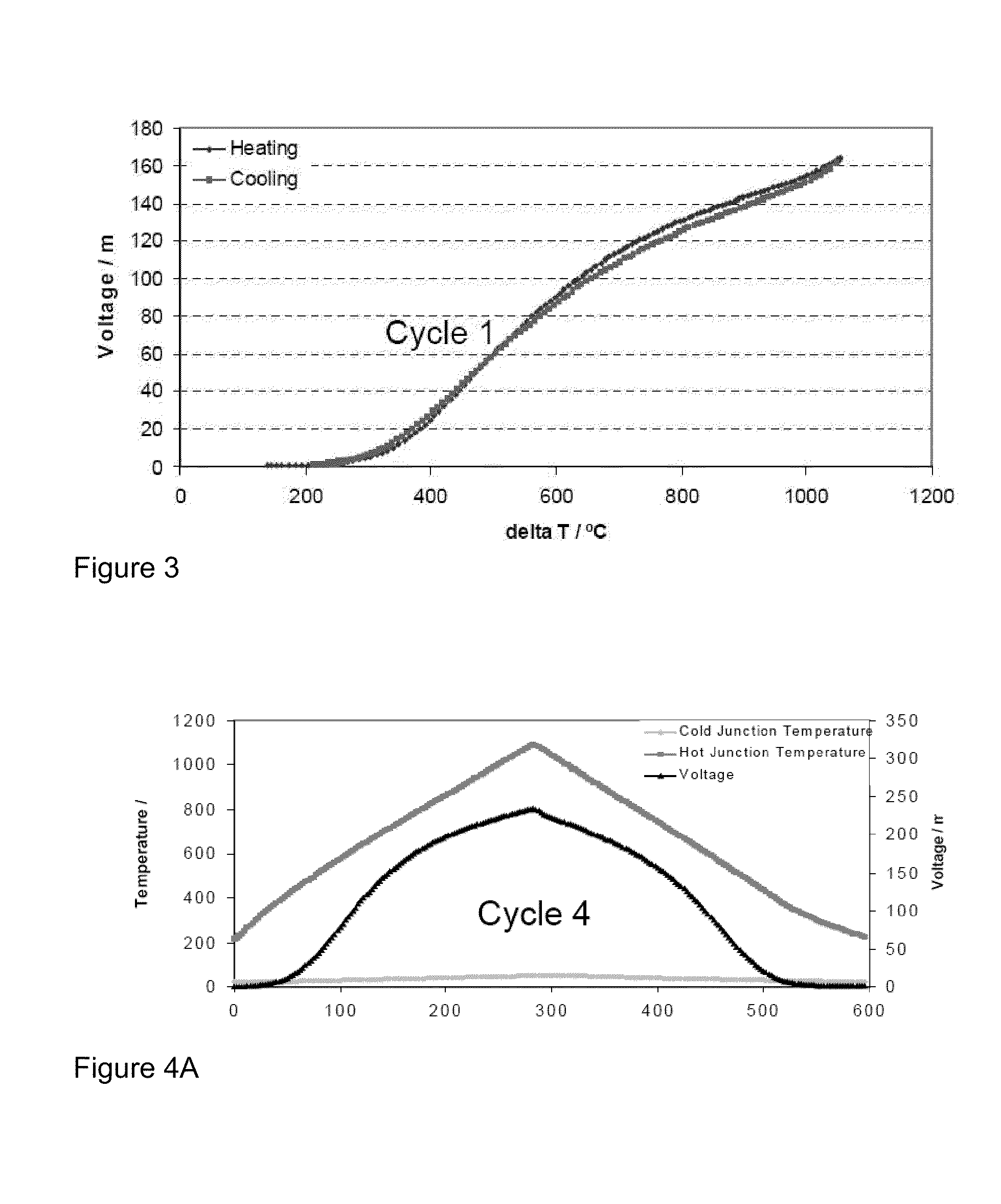
a technology of thermoelectric energy generators and nanocomposites, which is applied in the direction of instruments, heat measurement, calorimeters, etc., can solve the problems of material stability in high temperature environments, material thermodynamic stability in air ambients, and more significant challenges, and achieve low thermal conductivity and high voltage output

Inactive Publication Date: 2009-11-26
BOARD OF GOVERNORS FOR HIGHER EDUCATION STATE OF RHODE ISLAND & PROVIDENCE PLANTATIONS +1
View PDF8 Cites 30 Cited by
  • Summary
  • Abstract
  • Description
  • Claims
  • Application Information

AI Technical Summary

Benefits of technology

[0011]A nanocomposite cermet thermocouple material having a high voltage output and ultra low thermal conductivity, and is stable in hot oxid

Problems solved by technology

Based on these assessments, it is clear that temperature measurement is still the most critical measurement in the gas turbine engine environment and the technical challenge becomes more significant as operating temperatures are increased.
Other ceramic thermocouples have been considered for gas turbine applications based on silicides, nitrides and carbides but these materials are not thermodynamically stable in air ambients.
An earlier review of candidate materials for temperature measurement to 1650° C. by NASA indicated that materials stability in high temperature environments is the most critical issue for high temperature sensors.
Since these harsh environments will greatly affect sensor reliability, lifetime and performance, materials stability at high temperature is the overriding factor in the selection and design of sensors.
For example, the monitoring of temperature distribution and pattern factor in the combustion chamber of a gas turbine engine is critical since the lack of proper fuel burning can severely damage engine components and affect overall performance.
Batteries are impractical because they are difficult to replace and cannot operate at high temperatures, so a local power source is necessary.

Method used


Image

  • Nano-composites for thermal barrier coatings and thermo-electric energy generators
  • Nano-composites for thermal barrier coatings and thermo-electric energy generators
  • Nano-composites for thermal barrier coatings and thermo-electric energy generators

Examples


Embodiment Construction

[0027]Thin film thermocouples are non-intrusive in that the thermocouple thickness is considerably less than the gas phase boundary layer thickness. In addition, platinum and platinum / rhodium based thermocouples are prone to yield errors due to catalytic effects and can give results that can deviate by as much as 50° C. from the actual temperature. Also, thin film thermocouples based on platinum and platinum / rhodium have indicated serious oxidation problems related to the oxidation of rhodium in the temperature range (700-900° C.) and potentially damaging substrate reactions at temperatures above 1250° C. In addition, platinum and platinum / rhodium thermocouple elements are prone to signal drift when used above 1000° C. for prolonged periods due to deterioration of the mechanical properties via creep processes. These alloys are very expensive, even when used in thin film form. Thus, semi-conductive oxide thermocouples represent a cost effective alternative to temperature sensing when...


PUM

PropertyMeasurementUnit
Seeback coefficientaaaaaaaaaa
Temperatureaaaaaaaaaa
Electrical conductivityaaaaaaaaaa

Abstract

A nano-composite material having a high electrical conductivity and a high Seebeck coefficient and low thermal conductivity. The nano-composite material is capable of withstanding high temperatures and harsh conditions. These properties make it suitable for use as both a thermal barrier coating for turbine blades and vanes and a thermoelectric generator to power high temperature electronics, high temperature wireless transmitters, and high temperature sensors. Unique to these applications is that the thermal barrier coatings can act as a temperature sensor and / or a source of power for other sensors or high temperature electronics and wireless transmitters.

Description

PRIORITY INFORMATION[0001]This present application is a continuation of International Patent Application No. PCT / US2007 / 081778, filed on Oct. 18, 2007, which claims priority to U.S. Provisional Patent Application Ser. No. 60 / 852,489, filed on Oct. 18, 2006, all of which is incorporated herein in its entirety.GOVERNMENT SPONSORSHIP[0002]This invention was made with government support under Grant No. NNC05GA67G awarded by the National Aeronautic and Space Administration (NASA). The government has certain rights in the invention.BACKGROUND OF THE INVENTION[0003]In a recent Department of Energy / Oak Ridge National Laboratory report, the needs for sensors and controls for advance turbine systems were assessed and the highest priority need identified was the accurate measurement of combustion gas temperature and flame detection up to 1650° C. to enable closed loop control of emissions. Also identified in this report was the need for the development of durable sensors to control combustion ...

Claims


Application Information

Patent Timeline
IPC IPC(8): G01K17/00G01K7/02C23C16/06C23C14/34B05D1/08B05D1/36
CPCG01K7/02G01K7/028H01L35/26H01L35/22G01K2211/00H10N10/855H10N10/857
Inventor GREGORY, OTTO J.FRALICK, GUSTAVE C.WRBANEK, JOHN D.
Owner BOARD OF GOVERNORS FOR HIGHER EDUCATION STATE OF RHODE ISLAND & PROVIDENCE PLANTATIONS
Learn More