Data recovery system for source synchronous data channels

a data recovery and synchronous data technology, applied in the field of data recovery systems, can solve the problems of not meeting the cost, power, and size targets implied by the consumer market, and achieve the effects of reducing the number of data loss, and improving the reliability of the system

Active Publication Date: 2009-11-26
REDMERE TECH
View PDF17 Cites 30 Cited by
  • Summary
  • Abstract
  • Description
  • Claims
  • Application Information

AI Technical Summary

Benefits of technology

[0007]There is an object of the invention to provide

Problems solved by technology

Existing technologies commonly used in high performance telecommunications equipment could be employed to build HDMI

Method used


Image

  • Data recovery system for source synchronous data channels
  • Data recovery system for source synchronous data channels
  • Data recovery system for source synchronous data channels

Examples


Embodiment Construction

[0061]The data recovery system of the embodiment of the present invention is useful in applications where high speed data has been transmitted on one or more serial channels. Conveniently, data is sent along with the clock that is used for the generation of the data timings. The system is particularly effective when the data has been transmitted through a cable of a limited bandwidth, which results in considerable Inter Symbol Interference (ISI) in the data streams. The system is also extended to deal with intra-pair or differential skew in the cabling.

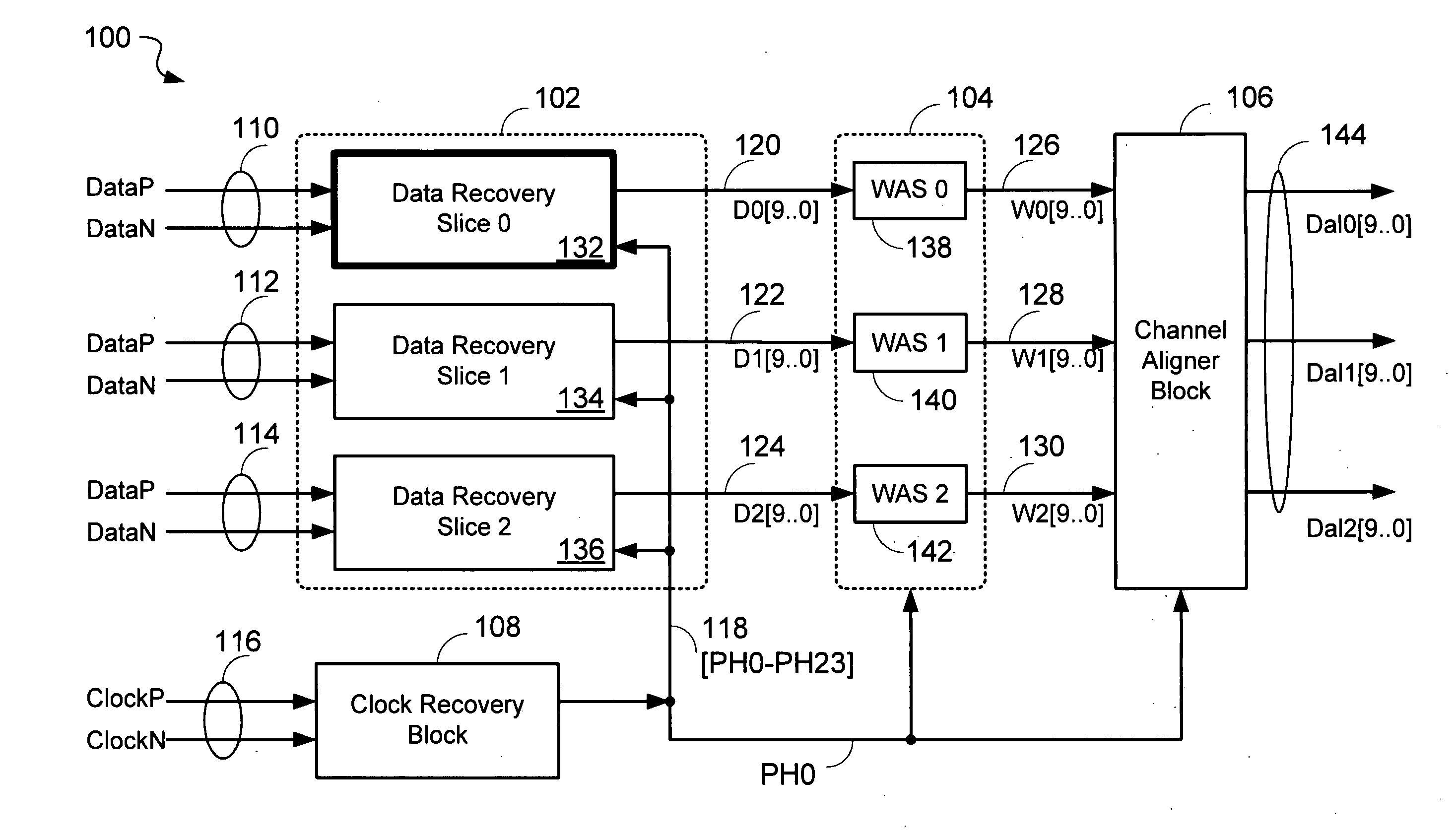
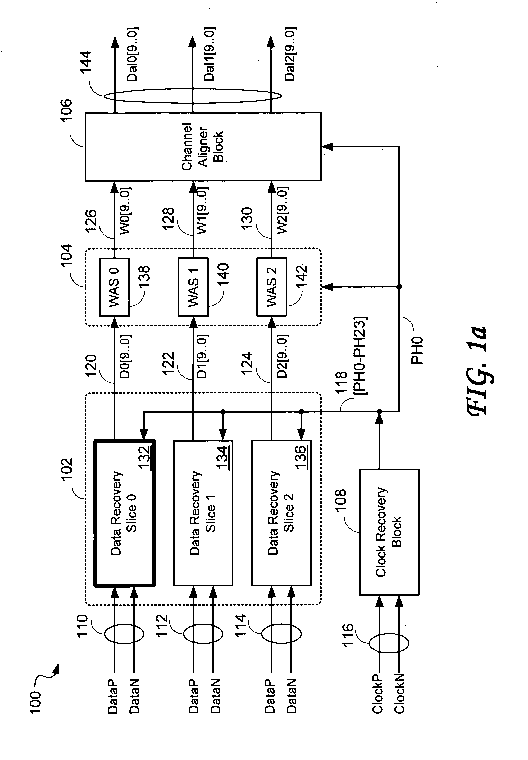
[0062]FIG. 1a shows a block diagram of a HDMI receive interface 100 of the embodiment of the present invention. The HDMI receive interface 100 comprises a Data Recovery Block 102; a Word Aligner Block 104; a Channel Aligner Block 106; and a Clock Recovery Block108. The overall function of the HDMI receive interface 100 is to recover the digital information sent to it from an HDMI source over a cable that includes 4 differential signal...


PUM


Abstract

A high-definition multimedia interface (HDMI) receiver recovers high speed encoded data which are transmitted differentially over data channels of a lossy cable, along with a clock. Inter symbol interference, high-frequency loss, skew between the clock and data channels, and differential skew within a differential signal are compensated by analog circuits which are automatically tuned for best performance by observing the quality of the recovered analog signal. Oversampling is used to provide a 24-bit digital representation of the analog signal for determining the quality of the signal.

Description

RELATED APPLICATIONS[0001]This application is a Continuation-in-Part (CIP) of the U.S. application Ser. No. 11 / 623,069 filed on Jan. 13, 2007 to Judith REA entitled “An Improved Data Recovery System For Source Synchronous Data Channels”, which claims priority from the U.S. provisional patent application Ser. No. 60 / 759,985 to Judith REA et al. entitled “An Improved Data Recovery System For Source Synchronous Data Channels” filed on Jan. 19, 2006, both applications being incorporated herein by reference.FIELD OF THE INVENTION[0002]The present invention relates to data recovery systems, and in particular, to an improved data recovery system for source synchronous data channels.BACKGROUND OF THE INVENTION[0003]The distribution of television signals has increasingly become based on digital methods and digitally encoded forms of video and audio signals. At the same time, higher resolution (high definition TV) has become available in the market place, commensurate with larger and higher d...

Claims


Application Information

Patent Timeline
IPC IPC(8): H04L7/00
CPCH04L25/0272H04L25/08H04L25/068H04L25/03885
Inventor REA, JUDITH ANNKEADY, AIDAN GERARDKEANE, JOHN ANTHONYHORAN, JOHN MARTIN
Owner REDMERE TECH
Why Eureka
Try Eureka